dIXEL
Operating and Instructions Manual
1592006100
1592006100 XB570L GB r1.0 04.11.2004.doc
XB570L
4/6
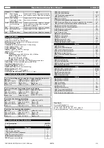
15.3.6 “rtC”: clock management (for XB570L only)
It contains the real time clock parameters:
SEC: seconds
(00÷59);
Min: Minutes
(00÷59);
Hou Current hour
(1÷24)
7dY
:
day of the week
(
Mon
= Monday,
tue
= Tuesday,
Wed
=
Wednesday,
thu
= Thursday,
Fri
= Friday,
Sat
= Saturday,
Sun
=
Sunday).
dAY: day of the month
(1÷31)
Mon: number of the month
(1÷12)
YEA: year
(0÷99)
15.3.7 “ALr”: alarms display
This function displays any alarm messages.
15.3.8 “Prt”: printer management
This menu is used for the management of the printer. It contains the
parameters:
PrP
printer presence: (Yes/no) Enabling or disabling the printer
itP:
printing interval: (0.0÷30.0 min) It sets the interval of printing.
PbP: Which probe print:
(,
iP:
Only the Insert probe;
rP:
Only the room
probe;
irP:
The Insert and the room probe;
irE:
All the probe)
PtH:
(yes/no) it enables or disables the printing during the holding
phase.
15.3.9 “tSt”:
it starts the instrument self test
.
15.3.10 “Out”: exits from menu.
16. Accessing “Pr2” and SECURITY CODE input
To access parameters in “
Pr2
” a security code is required.
1. Enter Function Menu, select label “
Pr2
” and press the “
SET
” key. The
“PAS” flashing message is displayed, shortly followed by “0 _ _” with a
flashing zero.
2. Use
“UP”
or
“DOWN”
to input the security code in the flashing digit;
3. Confirm the figure by pressing “
SET
”.
4. Repeat operations 2 and 3 for the other digits.
5. If the security code is correct the access to “
Pr2
” is enabled by pressing
“
SET
” on the last digit, otherwise the “rtC” menu is shown.
If no key is pressed for more than 15 seconds the instrument reverts to room
temperature display mode.
The default SECURITY CODE is
321 .
NOTA1:
the general security code is
981
. (please refer to parameter PAS)
NOTE2
: each parameter in “Pr2” can be removed or put into “Pr1” (user
level) by pressing
“SET
+
è
”
. In Pr2 when a parameter is present in “Pr1” or
“rtC” LED
is on.
17. List of parameters
REGULATION
HyIntervention differential for set point:
(0,1
÷
12,0 /0,1°C/1°F), always
positive. Compressor cut IN is Set Point Plus Differential (Hy).
Compressor cut OUT is when the temperature reaches the set point.
AC Anti-short cycle delay
: (0÷30 min) minimum interval between the
compressor stop and the following restart.
1c2 Second compressor setting: (enabled only if OAC=C2)
The fourth relay work as second compressor if OAC=Co2.
Second compressor operates on set + OAS. (whit set= set loaded during
the current phase). It starts oAt min. after the first compressor
The following table shows how it works:
Cycle
Holding
1c2=0
C1 ON; C2 On
C1 on; C2 On
1c2=1
C1 on; C2 On
C1 on C2 off
1c2=2
C1 on; C2 off
C1 on; C2 On
1c2=3
C1 on; C2 off
C1 off; C2 On
rPOThermostat probe calibration
(-12,0
÷
12,0; res. 0,1 °C /1°F)
EPP Evaporator probe presence (not present in the XB350C):
(no / YES)
no:
not present (timed defrost);
YES:
present (end defrost )
EPO Evaporator probe calibration (not present in the XB350C):
(-12,0
÷
12,0; res. 0,1 °C /1°F)
iPP Insert probe presence (
no / YES)
no:
not present;
YES:
present.
iPO Insert probe calibration
(-12,0
÷
12,0; res. 0,1 °C /1°F)
CF Temperature measurement unit
: °C =Celsius; °F =Fahrenheit
rES Resolution (for °C)
:
in
: integer;
de
: with decimal point
PAU Time of stand by:
(0
÷
60min) after this time the controller restart the
cycle
PFt Maximum acceptable duration of power failure:
(0
÷
250 min) if power
failure duration is less than PFt, the cycle restarts from the same point at
which it was stopped otherwise the cycle restarts from the beginning of
the current phase.
iPd Temperature difference for the automatic recognition of the insert
probe:
(0
÷
30; ris.1 °C/1°F) if the difference of temperature between the
insert probe and the thermostat probe is less than iPd, the selected cycle
is made by time.
iPtTime delay for the automatic recognition of the insert probe:
(0÷255sec, with 0 only timed cycles are done) time between the start of
a cycle and the comparison of the temperature of the thermostat probe
and the insert probe to recognising if the insert probe is used.
Con Compressor ON time with faulty probe
: (0
÷
255 min) time during
which the compressor is active in case of faulty thermostat probe. With
COn=0 compressor is always OFF
COF Compressor OFF time with faulty probe
: (0÷255 min) time during
which the compressor is off in case of faulty thermostat probe. With
COF=0 compressor is always active
diC Digital input operating mode
(EAL, bAL, dor)
EAL:
external alarm;
bAL:
serious alarm;
dor:
door open function
diP: digital input polarity:
(OP÷CL)select if the digital input is activated by
opening or closing the contact. OP= opening; CL=closing
did: digital input delay
(0÷255 min) delay between digital input activation
and his signalling for configurable or door opened alarm.
NOTE:
with
diC=EAL did
has to be
different from zero
.
OAC: AUX output configuration:
(AL, Li, UL, Ip, AA, rE, dF, C2)
AL:
alarm output;
Li:
light of the cabinet;
UL:
for the ultra-violet light (It is
actionable only when the controller is in OFF position);
Ip:
to extract the
insert probe
(It is actionable only when the controller is in OFF position);
AA:
anti - condensation;
rE:
the IV relay works as a thermostat, with
direct action (cooling) (OAH>0), and inverse actions (heating) (OAH<0);
dF:
the IV relay is activated during the defrost, at the end of the defrost it
remains ON for the OAt time;
C2:
second compressor. See 1c2
parameter for different settings.
OAP
AUX output polarity (
OP
÷
CL)
OP
= normally open; if it is ON the
terminals 6-8 are closed.
CL
= normally closed; if it is ON the terminals 6-
7 are closed.
OAt AUX output timer
: (0÷255 min) time in which the AUX output stays ON.
It is enabled when OAC = Li or UL or Ip or AA or dF.
OAS Set point for AUX output
(-50÷50; ris.1 °C/ 1°F)
OAH Differential for AUX output:
(-12.0
÷
12,0; ris.0,1°C/1°F, always
≠
0)
Intervention differential for the set point of the auxiliary, with OAH<0 the
action is for heating, with OAH>0 it is for cooling.
COOLING:
AUX cut IN
is OAS Plus Differential (OAH>0). AUX cut OUT is when the temperature
reaches the set point OAS.
HEATING:
AUX cut IN is OAS Plus Differential (OAH<0). AUX cut OUT is
when the temperature reaches the set point OAS.
OAi Probe selection for the AUX output (rP, EP, iP)
rP = thermostat probe,
EP = evaporator probe; iP = insert probe
DEFROST
tdF Defrost type (not present in the XB350C)
: (
rE
= electrical heater;
in
=
hot gas).
dPO Defrost before the holding: no
= no defrost;
YES
= defrost at the start
of a holding cycle.
IdF Interval between defrost cycles
: (0.1
÷
24.0; res. 10 min) Determines
the time interval between the beginning of two defrost cycles. (with 0.0
the defrost is disabled)
dtE Defrost termination temperature (not present in the XB350C)
: (-
50
÷
50 °C/°F) Sets the temperature measured by the evaporator probe,
which terminates the defrost.
MdF Maximum length for defrost
: (0÷255 min) When EPP = no (timed
defrost) it sets the defrost duration, when EPP = YES (defrost
termination based on temperature) it sets the maximum length for
defrost.
dFd Temperature displayed during defrost
: (rt , it, SEt, dEF
) rt:
real
temperature;
it:
temperature at the start of defrost;
SEt:
set point;
dEF:
“dEF” message
Fdt Drip time (not present in the XB350C)
: (0
÷
60 min) Time interval
between reaching defrost termination temperature and the restoring of
the controllers' normal operation. This time allows the evaporator to
eliminate water drops that might have formed during defrost.
FANS
FnC Fans operating mode during the holding phase
:
C-n
= runs with the compressor, OFF during defrost;
o-n
= continuous
mode, OFF during defrost;
C-Y
= runs with the compressor, ON during
defrost;
o-Y
= continuous mode, ON during defrost;
FSt Fan stop temperature
: (-50÷50°C/°F; res. 1°C/1°F) if the temperature,
detected by the evaporator probe is above FSt fans are stopped. It
serves to avoid blowing warm air around the room.
AFH Differential for the stop temperature and for the alarm
(0.1
÷
25.0
°C; ris.0.1°C/1°F) Fans carry on working
when the temperature reaches
the FSt-AFH value, the temperature alarm recovers when the
temperature is AFH degrees below the alarm set.
Fnd Fan delay after defrost:
(0
÷
255 min) The time interval between end of
defrost and evaporator fans start.
ALARM
ALU MAXIMUM temperature alarm
: (1
÷
50 °C/°F) When the “SET+ALU”
temperature is reached the alarm is enabled, (possibly after the “Ald”
delay time).


