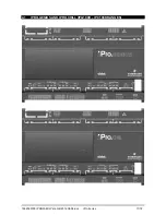
1592025700 IPROFAMILY stp GB 2012.08.08.doc
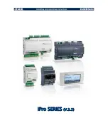
iPro Series
13/72
4.1.2
Description of the inputs and outputs
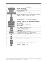
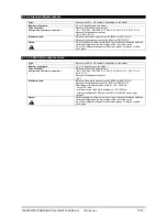
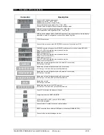
Input
No.
Type of Input
Description
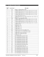
1 Supply
Reference “-“/GND power (24Vac or 24Vdc)
2
Pb1
Configurable analogue input 1 (NTC, PTC, 0 - 20mA, 4 - 20mA, 0 - 10V, 0 - 1V, 0 - 5V, DI)
3
Pb2
Configurable analogue input 2 (NTC, PTC, 0 - 20mA, 4 - 20mA, 0 - 10V, 0 - 1V, 0 - 5V, DI)
4
Pb3
Configurable analogue input 3 (NTC, PTC, 0 - 20mA, 4 - 20mA, 0 - 10V, 0 - 1V, 0 - 5V, DI)
5
Pb4
Configurable analogue input 4 (NTC, PTC, 0 - 20mA, 4 - 20mA, 0 - 10V, 0 - 1V, 0 - 5V, DI)
6
Pb5
Configurable analogue input 5 (NTC, PTC, 0 - 20mA, 4 - 20mA, 0 - 10V, 0 - 1V, 0 - 5V, DI)
7
PbC
Common analogue inputs (NTC, PTC, DI)
8 GND
(-)
Additional power reference 5Vdc and 12Vdc and analogue inputs (0 - 20mA, 4 - 20mA, 0 - 10V,
0 - 1V, 0 - 5V)
9 Supply
Reference “+“ power supply (24Vac or 24Vdc)
10
Pb6
Configurable analogue input 6 (NTC, PTC, 0 - 20mA, 4 - 20mA, 0 - 10V, 0 - 1V, 0 - 5V, DI)
11
Pb7
Configurable analogue input 7 (NTC, PTC, 0 - 20mA, 4 - 20mA, 0 - 10V, 0 - 1V, 0 - 5V, DI)
12
Pb8
Configurable analogue input 8 (NTC, PTC, 0 - 20mA, 4 - 20mA, 0 - 10V, 0 - 1V, 0 - 5V, DI)
13
Pb9
Configurable analogue input 9 (NTC, PTC, 0 - 20mA, 4 - 20mA, 0 - 10V, 0 - 1V, 0 - 5V, DI)
14
Pb10
Configurable analogue input 10 (NTC, PTC, 0 - 20mA, 4 - 20mA, 0 - 10V, 0 - 1V, 0 - 5V, DI)
15 +5V
Additional
power
+5Vdc
16 +12V
Additional
power
+12Vdc
21
Out1
Analogue output 1 0 - 10V
22
Out2
Analogue output 2 0 - 10V
23
Out3
Analogue output 3 0 - 10V
24
Out4
Analogue output 4 0 - 10V
25
GND(-)
Additional power reference 12Vdc and analogue outputs
26
Out5
Analogue output 5 0 - 10V, 4 - 20mA, Relay (if TF1 is not used)
27
Out6
Analogue output 6 0 - 10V, 4 - 20mA, Relay (if TF2 is not used)
28
TF1
Analogue output TF1 PWM (if Out5 is not used)
29
TF2
Analogue output TF2 PWM (if Out6 is not used)
30 +12V
Additional
power
+12Vdc
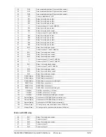
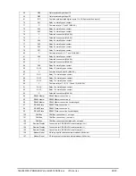
40
DI1
Opto-insulated digital input 1 (potential free contact)
41
DI2
Opto-insulated digital input 2 (potential free contact)
42
DI3
Opto-insulated digital input 3 (potential free contact)
43
DI4
Opto-insulated digital input 4 (potential free contact)
44
DI5
Opto-insulated digital input 5 (potential free contact)
45
DI6
Opto-insulated digital input 6 (potential free contact)
46
DI7
Opto-insulated digital input 7 (potential free contact)
47
DI8
Opto-insulated digital input 8 (potential free contact)
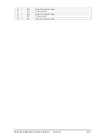
48
DI9
Opto-insulated digital input 9 (potential free contact)
49
DI10
Opto-insulated digital input 10 (potential free contact)
50
DIC
Common opto-insulated digital inputs 1 to 20
51
DI11
Opto-insulated digital input 11 (potential free contact)
52
DI12
Opto-insulated digital input 12 (potential free contact)
53
DI13
Opto-insulated digital input 13 (potential free contact)
54
DI14
Opto-insulated digital input 14 (potential free contact)
55
DI15
Opto-insulated digital input 15 (potential free contact)
56
DI16
Opto-insulated digital input 16 (potential free contact)
57
DI17
Opto-insulated digital input 17 (potential free contact)
Summary of Contents for iPro SERIES
Page 1: ...iPro SERIES V 3 2 ...
Page 2: ......
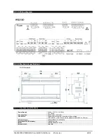
Page 18: ...1592025700 IPROFAMILY stp GB 2012 08 08 doc iPro Series 18 72 4 1 3 6 Wiring diagrams ...
Page 20: ...1592025700 IPROFAMILY stp GB 2012 08 08 doc iPro Series 20 72 4 2 IPRO GENIUS IPG200D RANGE ...
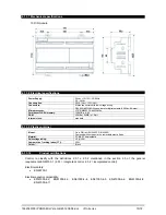
Page 54: ...1592025700 IPROFAMILY stp GB 2012 08 08 doc iPro Series 54 72 5 1 4 Dimensions ...
Page 72: ...1592025700 IPROFAMILY stp GB 2012 08 08 doc iPro Series 72 72 ...

