background image

18

Dixon Industries, Inc. •  Airport Industrial Park  •  Coffeyville, KS •  67337 • 620-251-2000

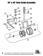
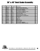
36” & 48” Front Caster Assembly

Item No. MFG Code

Part Number Description

Qty

1

200-026

11726

Grease Fitting M6 GB1152-89

4

2

200-003

12808

Hexagon Bolt M10*25 GB 5783-86

8

3

200-006

11706

Nylon Nut M10 GB889-86

4

4

200-010

3057

Plain Washer 10 GB95-85

4

5

200-031

3065

Lock Washer 10 GB93-87 (For 36")

2

6

100-092

11592

Castor Wheel Assembly W

2

7

100-093

11593

Pivot Tube, Castor

2

9

100-015

11515

Plain Washer 2*26 id *38 od

2

12

200-057

11757

Hexagon Bolt M12*140 GB5782-86

2

13

100-096

11596

Castor Yoke 

2

14

100-097

11597

Lynch Pin

2

15

100-098

11598

Spacer 13

6

16

100-099

11599

Spacer 6.5

2

17

100-100

11600

Bushing, Castor

4

18

100-101

11601

Castor Support 

2

19

200-007

11707

Nylon Nut M12 GB889-86

2

20

200-006

11706

Nylon Nut M10 GB889-86 (For 48")

4

Summary of Contents for 36 & 48

Page 1: ...rk Coffeyville KS 67337 620 251 2000 www dixon ztr com Congratulations on the purchase of your new Dixon mower Before any warranty service can be authorized you must register this product with the manufacturer Dixon Industries Inc 36 48 Commercial Belt Drive Mowers ...

Page 2: ...ing Blades 12 Adjusting Front Wheels 12 Service And Maintenance Of The Mower Maintenance Schedule 14 Fuel 15 Engine Oil 15 Air Filter 15 Tire Pressure 15 Blades 15 Cleaning The Mower 15 Lubrication Points 16 Service Adjustments Wheel Brake Adjustments 17 Wheel Brakes 17 Engine To Blade Belt 18 Blade To Blade Belt 19 Engine To Transmission Belt 19 Safety Interlock System 19 Troubleshooting Guide 20...

Page 3: ... _______________________________________________ _______________________________________________ _______________________________________________ _______________________________________________ _______________________________________________ _______________________________________________ _______________________________________________ _______________________________________________ _______________...

Page 4: ...w Dixon commercial mower We at Dixon Industries Inc are confident that this mower will provide you with years of excellent performance durability and trouble free service when operated and maintained as directed in this manual Should you ever have any questions regarding the operation maintenance or safety of your mower please contact your authorized Dixon Mower dealer who has been specially train...

Page 5: ... or alteration The use of parts or components other than those supplied by Dixon Industries VOIDS ALL WARRANTY 5 The following items are not covered by this warranty policy a Pick up and delivery charges for transportation of mower to and from an authorized Dixon dealer s place of business b Routine maintenance or adjustments c Belts blades tilters or tires d Engines all engines used on Dixon Walk...

Page 6: ...n objects When struck by the mower these and other objects my become projectiles that could lead to serous injury and or death Mower For your safety and the long life of your mower always inspect the mower before each use Before inspection make sure it is on a flat and level surface the blades are disengaged the ignition switch off with the key removed and the spark plug wire is off of the spark p...

Page 7: ...n when changing directions or speed when operating on a slope Be extremely careful when operating on a slope or when the grass is damp or wet Reduced traction could cause sliding Never mow by pulling the mower back towards you you might slip Watch for traffic when crossing surfaces other than grass i e transporting loading a trailer or vehicle or when the mower is not in use Never operate the mowe...

Page 8: ... SAFETY INFORMATION DECALS The following labels are intended to alert you to potential hazards and to provide you with important safety information Should these decals become difficult to read or are missing from the mower contact your Dixon WalkAbout Mower dealer for a replacement ...

Page 9: ...When reading this manual it is recommended that you do so with the equipment nearby for quick orientation reference of controls and maintenance adjustments Operating Controls Before continuing to read the manual it is recommended that you take adequate time to identify the controls of the mower A Traction Lever Locks D Key Switch B Operator Presence Controls E Throttle Choke Control C Blade Contro...

Page 10: ...firmly with a smooth steady motion to start the engine When the engine starts to run slowly return the engine speed control out of CHOKE to the desired engine speed Going Forward CAUTION Become totally familiar with the operation and characteris tics of the mower before attempting to actually mow with it Making sure that the traction control levers are in the neutral position push down and hold th...

Page 11: ...nd evenly let both traction control levers down simultaneously and the mower will start to go in reverse Always use extreme caution when moving the mower backwards and never move the mower downhill backwards To stop the mower slowly and evenly squeeze up on both control levers until the mower comes to a complete stop and then with your thumbs push down on the traction lever locks until the levers ...

Page 12: ...tting height on a hard surface such as concrete the mower will usually mow about 1 4 lower in grass due to the weight of the machine Removing And Adjusting The Blades CAUTION Beware of the cutting edges on the blades The rotation of one blade may cause the other blade s to rotate Always wear work gloves when handling blades Park the mower on level ground and block the rear wheels to prevent accide...

Page 13: ...13 Dixon Industries Inc Airport Industrial Park Coffeyville KS 67337 620 251 2000 Figure 6 Figure 7 Figure 8 ...

Page 14: ... ACCIDENTAL CONTACT IF ADJUSTMENT OR MAINTENANCE IS BEING PERFORMED AFTER OPERATION OF THE MOWER ALLOW THE UNIT TO COOL SINCE HEAT BUILD UP COULD CAUSE SEVERE BURNS Maintenance Schedule Time Interval Item Procedure Break in first 5 hrs Every 8 hours Daily Every 40 hours Weekly Every 100 hours Bi weekly Every 200 hours Monthly Belts Inspect adjust if needed Blades Inspect and Sharpen Engine Air Fil...

Page 15: ...ssure may cause the mower to pull to one side and or an uneven cut Always use caution when filling the tire and never exceed the rec ommended tire pressure Blade DANGER BEFORE WORKING ON THE BLADES MAKE SURE THE ENGINE IS OFF KEY REMOVED AND THE SPARK PLUG S WIRES REMOVED FROM THE SPARK PLUG S TO PREVENT ACCIDENTAL CONTACT CAUTION Beware of the cutting edges on the blades Always wear work gloves w...

Page 16: ...erval may be shorter than recommended GTR OPE Grease is the recommended lubricant Transmission Output Shaft Left Ride Sides Every 40 hrs Weekly Blade Engagement Bellcrank Every 40 hrs Weekly Blade Engagement Pivot Left Right Sides Every 40 hrs Weekly Cutterhousings Every 100 hrs Monthly Front Caster Wheel Left Right Sides Every 40 hrs Weekly Front Caster Support Left Right Sides Every 40 hrs Weekl...

Page 17: ...ely 1 2 clearance between the bottom of the traction control rod and the bottom of the slot in traction control lever lock A figure 10 5 While holding the rod in place rotate swivel B on the traction control rod D until the swivel realigns with the hole in idler arm C Push the swivel through the idler arm hole and secure with the flat washer and hair pin cotter Repeat for the other side Wheel Brak...

Page 18: ...de control lever on the control console to the ON position 2 With approximately 10 lbs of pressure being applied on the engine to blade belt midway between the pulleys refer to the appropriate figure for your mower the belt should move approximately 1 2 3 If the belt moves more than 1 2 move the blade control lever back to the OFF position 4 Remove hair pin cotter A and the flat washer from swivel...

Page 19: ...t Refer to figure 14 1 The engine to transmission belt located underneath the rear deck should move 3 16 with 5 lbs of pressure applied midway on the belt between the transmission pulley and the engine output shaft pulley 2 To adjust the belt loosen nut A on idler pulley B 3 Slide idler pulley B to tighten or loosen and secure in place by tightening nut A Figure 15 Safety System Adjustment Refer t...

Page 20: ...just switches Page 19 adjustment Throttle control not in the choke Move throttle control to choke position Spark plug loose or disconnected Connect spark plug wire Bad spark plug Replace Dirty air filter Replace Clogged fuel filter Replace Bad fuel Drain and refill with fresh fuel Engine Starts Hard Or Dirt or water in the fuel tank Drain and clean fuel tank Loose Power Clogged or dirty fuel filte...

Page 21: ...essure not the same in both Check and adjust page 15 drive wheels Uneven Cut Blade belt broken or slipping Replace or adjust Excessive build up underneath Check and clean mowing deck Rough Cut Unequal space configuration on Check and adjust page 13 blades or front casters Ground speed too fast for Reduce travel speed mowing conditions Blades bent Check and replace page 12 Tire pressure in wheels n...

Page 22: ...1 Dixon Industries Inc Airport Industrial Park Coffeyville KS 67337 620 251 2000 36 Frame Assembly ...

Page 23: ...t M12 25 GB5783 86 6 12 200 005 11705 Hexagon Head Bolt M10 240 GB5782 86 1 13 100 007 Blue 11507 Chute Deflector 1 14 100 008 11508 Torsion Spring 1 15 200 006 11706 Nylon Nut M10 GB889 86 not shown 17 17 200 007 11707 Nylon Nut M12 GB889 86 6 18 200 021 3020 Plain Washer 8 GB95 85 2 21 100 009 11509 Saucer Nut 4 22 200 006 11706 Nylon Nut M10 GB889 86 2 23 200 008 11708 Hexagon Bolt M10 110 GB57...

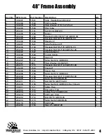
Page 24: ...3 Dixon Industries Inc Airport Industrial Park Coffeyville KS 67337 620 251 2000 48 Frame Assembly ...

Page 25: ...2 86 1 13 100 007 11507 Chute Deflector 1 14 100 008 11508 Torsion Spring 1 16 148 002 11642 Deck 48 1 17 200 007 11707 Nylon Nut M12 GB889 86 6 18 200 021 3020 Plain Washer 8 GB 95 85 2 19 200 015 11715 Hexagon Bolt M10 140 GB5783 86 3 20 148 003 11643 Hood 48 1 21 100 009 11509 Saucer Nut 3 22 200 006 11706 Nylon Nut M10 GB889 86 5 23 200 008 11708 Hexagon Bolt M10 110 GB5782 86 2 24 200 009 117...

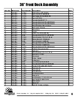
Page 26: ...5 Dixon Industries Inc Airport Industrial Park Coffeyville KS 67337 620 251 2000 36 Front Deck Assembly ...

Page 27: ...Blade Idler Arm Weldment 1 17 200 021 3020 Plain Washer 8 GB95 85 1 18 200 022 11722 Hexagon Bolt M10 65 GB5782 86 1 19 200 010 3057 Plain Washer 10 GB95 85 5 20 200 018 11718 Hexagon Bolt M10 35 GB5783 86 8 21 100 021 11521 Cutting House Assembly 2 22 100 022 11522 Spacer 6 10 24 100 023 11523 Plain Washer 3 16 5 id 50 od 2 25 200 023 11723 Bolt M16 1 5 245 2 26 100 024 11524 Pivot Hub 1 27 100 0...

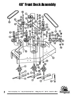
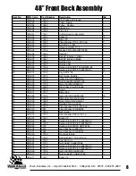
Page 28: ...7 Dixon Industries Inc Airport Industrial Park Coffeyville KS 67337 620 251 2000 48 Front Deck Assembly ...

Page 29: ...91 86 1 23 200 029 11729 Nut Flange M8 GB6187 86 1 24 200 030 11730 Nylon Nut M8 GB889 86 1 25 148 008 11648 Idler Pulley IV with Flange 1 26 100 018 11518 Swivel 1 27 100 017 11517 Blade Rod 1 28 200 006 11706 Nylon Nut M10 GB889 86 22 29 100 020 11520 Blade Idler Arm Weldment 1 30 148 009 11649 Deck Idler Arm Weldment 1 31 148 010 11650 Rod Belt Tension Hook 1 32 100 019 11519 Plain Washer 3 10 ...

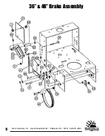
Page 30: ...9 Dixon Industries Inc Airport Industrial Park Coffeyville KS 67337 620 251 2000 36 48 Brake Assembly ...

Page 31: ...11747 Snap Ring 16 GB894 1 86 2 11 100 120 11620 Plain Washer 2 16 id 26 od 4 12 100 040 11540 Brake Link 4 13 200 032 11732 Hexagon Bolt M10 50 GB5782 86 2 14 200 016 11716 Nut Flange M10 GB6187 86 2 16 100 041 11541 Brake Lever Mount 2 19 200 008 11708 Hexagon Bolt M10 110 GB5782 86 2 20 100 003 11503 Plain Washer 2 10 5 id 26 od 4 21 100 004 11504 Pivot Tube 2 22 200 014 11714 Cotter Pin 2 20 G...

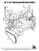
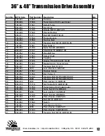
Page 32: ...11 Dixon Industries Inc Airport Industrial Park Coffeyville KS 67337 620 251 2000 36 48 Transmission Drive Assembly ...

Page 33: ...16 100 054 11554 Coupling 2 17 200 026 11726 Grease Fitting M6 GB1152 89 2 18 100 055 11555 Neutral Switch Transmission 1 20 200 037 11737 Hexagon Bolt 5 16 18 4 21 200 024 3019 Lock Washer 8 GB93 87 4 22 100 057 11557 Traction Spring 2 23 100 058 11558 Idler Pulley II 2 24 200 032 11732 Hexagon Bolt M10 50 GB5782 86 2 25 200 038 3384 Hexagon Bolt M10 60 GB5782 86 2 26 200 010 3057 Plain washer 10...

Page 34: ...13 Dixon Industries Inc Airport Industrial Park Coffeyville KS 67337 620 251 2000 36 48 Rear Deck Assembly ...

Page 35: ... 3057 Plain Washer 10 GB95 85 2 13 200 006 11706 Nylon Nut M10 GB889 86 for 48 1 14 100 065 11565 Idler Pulley III 1 15 100 025 11525 Pulley Single 1 16 100 066 11566 Key 6 35 6 25 2 17 100 067 11567 Pulley Input 1 18 200 016 11716 Nylon Nut M10 GB889 86 for 48 1 19 200 009 11709 Nylon Nut M6 GB889 86 2 20 100 068 11568 Belt Guide III 1 21 100 069 11569 Belt Guide IV 1 22 200 030 11730 Nylon Nut M...

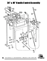
Page 36: ...15 Dixon Industries Inc Airport Industrial Park Coffeyville KS 67337 620 251 2000 36 48 Handle Control Assembly ...

Page 37: ...ease Fitting M6 GB1152 89 1 22 100 079 11579 Bell Crank Mount Bracket 1 23 100 080 11580 Blade Rod Traction Control Lever 1 26 200 054 11754 Hair Pin Cotter 2 1 28 200 006 11706 Nylon Nut M10 GB889 86 5 29 200 010 3057 Plain Washer 10 GB95 85 4 30 100 081 11581 Compression Spring 1 31 200 032 11732 Hexagon Bolt M10 50 GB5782 86 1 33 100 082 11582 Blade Control Lever 1 34 100 045 11545 Flat Grip 1 ...

Page 38: ...17 Dixon Industries Inc Airport Industrial Park Coffeyville KS 67337 620 251 2000 36 48 Front Caster Assembly ...

Page 39: ...sher 10 GB95 85 4 5 200 031 3065 Lock Washer 10 GB93 87 For 36 2 6 100 092 11592 Castor Wheel Assembly W 2 7 100 093 11593 Pivot Tube Castor 2 9 100 015 11515 Plain Washer 2 26 id 38 od 2 12 200 057 11757 Hexagon Bolt M12 140 GB5782 86 2 13 100 096 11596 Castor Yoke 2 14 100 097 11597 Lynch Pin 2 15 100 098 11598 Spacer 13 6 16 100 099 11599 Spacer 6 5 2 17 100 100 11600 Bushing Castor 4 18 100 10...

Page 40: ... 2 100 103 11603 Fuel Tank Body 1 3 100 104 11604 Fuel Tank Strap 2 4 200 058 11758 Hexagon Bolt M6 50 GB5782 86 2 5 200 042 3066 Plain Washer M6 GB95 85 2 6 200 009 11709 Nylon Nut M6 GB889 86 2 7 100 105 11605 Fuel Shut Off Valve 1 8 100 106 11606 Fuel Line 1 9 200 059 3649 Fuel Line Clamp 4 10 100 107 11607 Tank Pad 2 11 100 108 11608 Fuel Filter 1 12 100 109 11609 Tube Insert 1 ...

Page 41: ...k Washer 8 GB93 87 8 6 200 060 11760 Bolt M8 40 GB787 86 8 7 200 061 11761 Bearing 6005 2RS 4 8 100 113 11613 Valve 2 9 200 026 11726 Grease Fitting M6 GB1152 89 2 11 148 013 11653 Rim 36 48 2 13 100 019 11519 Plain Washer 3 10 5 id 38 od 2 14 100 119 11619 Bolt M10 left 1 15 200 003 12808 Hexagon Bolt M10 25 GB5782 86 1 16 100 099 11599 Spacer 6 5 for 36 48 2 17 148 012 11652 Tire 13X6 50 6 for 3...

Page 42: ... KS 67337 620 251 2000 36 48 Electrical Components Item No MFG Code Part Number Description Qty 1 100 060 11560 Switch 3 2 200 062 11762 Wire Tie 4 3 4 100 114 11614 Key Switch Key 1 5 100 115 11615 Wiring Harness 1 6 100 055 11555 Neutral Switch Transmission 1 ...

Page 43: ... _______________________________________________ _______________________________________________ _______________________________________________ _______________________________________________ _______________________________________________ _______________________________________________ _______________________________________________ _______________________________________________ _______________...

Page 44: ... Dixon Industries Inc Dixon Industries Inc Airport Industrial Park Coffeyville KS 67337 620 251 2000 ...

Reviews: