1
1
2
3
MAINTENANCE
43
8065-049
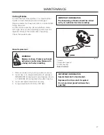
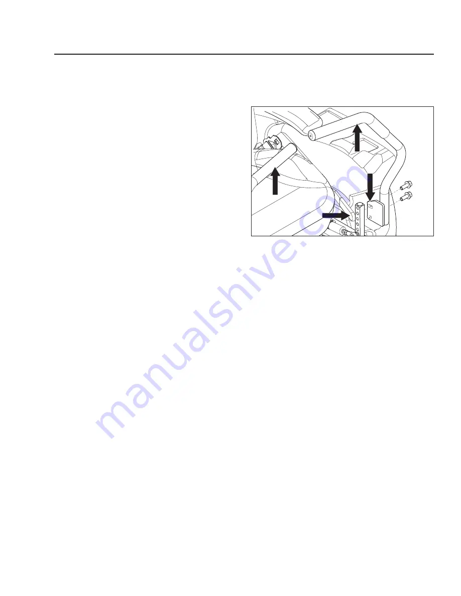
1. Drive levers
2. Control assembly
3. Alignment slot
Neutral adjustment
Drive Lever Adjustment
Drive levers can be adjusted up and down and side to
side to suit the operator.
Height Adjustment
Alignment adjustments will be needed after adjusting
the height. Make adjustments with the unit turned off.
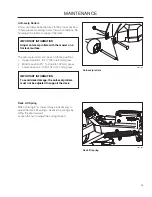
1. Remove the bolts securing the drive levers to the
control assembly.
2. Position the drive lever at the desired height and
reinstall the bolts, but do not fully tighten the bolts
at this time.
Alignment
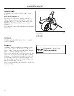
To align the drive levers uniformly, rotate both drive
levers inward and press both levers all of the way
forward.
1. Rotate the drive levers in the upper slots of the
lever until the levers are aligned with each other.
Tighten bolts on each drive lever securely.
Summary of Contents for 966651601
Page 58: ...WIRING DIAGRAM 58...
Page 70: ...SERVICE JOURNAL Action Date mtr reading stamp sign 71...
Page 71: ......
Page 72: ......


