background image

CONTROLS

17

This operator’s manual describes the Dixon Zero Turn 
Rider. The rider is fitted with a four-stroke overhead 
valve engine.
Transmission from the engine is made via belt-driven 

hydraulic pumps. Using the left and right steering 
controls, the flow is regulated and thereby the 
direction and speed.

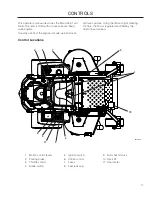
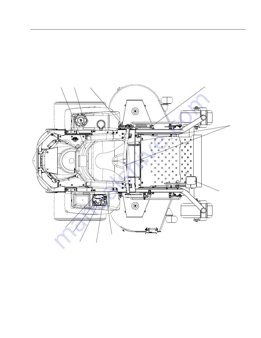
Control Locations

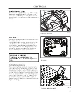
8050-080

1.  Motion control levers
2.  Parking brake
3.  Throttle control
4.  Blade switch

5.  Ignition switch
6.  Choke control
7.  Fuses
8.  Fuel tank cap

9.  Fuel shut off valve
10.  Deck lift
11.  Hour meter

1

2

6

10

9

8

4

5

11

7

3

Summary of Contents for 966690603

Page 1: ...use in this machine The use of any gasoline exceeding 10 ethanol E10 will void the product warranty Please read the operator s manual carefully and make sure you understand the instructions before us...

Page 2: ...tions and designs can be altered without prior notification Note that no legal demands can be placed based on the information contained in these instructions Use only original parts for repairs The us...

Page 3: ...ERATION 24 Training 24 Steering 24 Before Starting 25 Starting the Engine 25 Weak Battery 28 Jumper cables 28 Running 29 Operating On Hills 30 Mowing Tips 31 Stopping the Engine 32 Moving Machine by H...

Page 4: ...d mind and body and must not be under the influence of any mind altering substance WARNING Engine exhaust some of its constituents and certain vehicle components contain or emit chemicals known to the...

Page 5: ...ing equipment and ensure that the machine is well anchored DO NOT operate this machine on public roadways Towing If machine is equipped with a tow hitch use extreme caution when towing Never allow chi...

Page 6: ...machine s manufacturing number can be found on the printed plate affixed to the left in the engine compartment Stated on the plate from the top are The machine s type designation I D The manufacturer...

Page 7: ...cularly if the reader should neglect to follow instructions given in the manual Used in this publication to notify the reader of a risk of material damage particularly if the reader should neglect to...

Page 8: ...or s Manual Shut off engine and remove key before performing any maintenance or repair work Keep a safe distance from the machine Use on slopes no greater than 10 No passengers Whole body exposure to...

Page 9: ...e person Do not mow in reverse unless absolutely necessary Always look down and behind before and while backing Never direct discharged material toward anyone Avoid discharging material against a wall...

Page 10: ...riding mower related injuries These operators should evaluate their ability to operate the riding mower safely enough to protect themselves and others from serious injury Follow the manufacturer s re...

Page 11: ...n the machine Tall grass can hide obstacles Choose a low ground speed so that you will not have to stop while on the slope Do not mow on wet grass Tires may lose traction Avoid starting stopping or tu...

Page 12: ...alert to the presence of children Children are often attracted to the machine and the mowing activity Never assume that children will remain out of the path of danger Keep children out of the mowing a...

Page 13: ...beginning to refuel minimize the risk of static electricity by touching a metal surface Never fill containers inside a vehicle or on a truck or trailer bed with plastic liner Always place containers o...

Page 14: ...gularly to be sure it works properly The machine must not be driven with defective or unmounted protective plates protective cowlings safety switches or other protective devices Do not change the sett...

Page 15: ...by the following routines Never use the machine indoors or in spaces lacking proper ventilation The exhaust fumes contain carbon monoxide an odorless poisonous and lethal gas Stop to inspect the equi...

Page 16: ...the drive system Load the unit onto truck or trailer by driving up ramps of suitable strength using a slow speed Do not lift The machine is not intended to be lifted by hand When loading or unloading...

Page 17: ...e via belt driven hydraulic pumps Using the left and right steering controls the flow is regulated and thereby the direction and speed Control Locations 8050 080 1 Motion control levers 2 Parking brak...

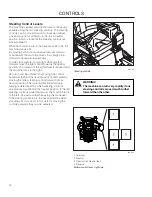
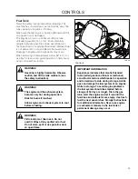
Page 18: ...he rotation of the right wheel is reduced and the machine turns to the right Zero turn can be achieved by moving one control backward behind the neutral position and carefully moving the other steerin...

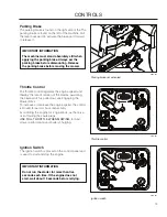
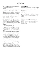
Page 19: ...on the right side of the The parking brake is found on the left of the machine Pull the lever backward to activate the brake and forward to release it IMPORTANT INFORMATION The machine must stand abs...

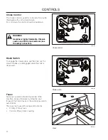
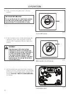
Page 20: ...safety instruction 8050 081 Choke control Blade Switch To engage the mower deck pull the knob out the mower blades are disengaged when the knob is depressed 8050 081 Blade switch Fuses Fuses are loca...

Page 21: ...n position and then engage and disengage the blade switch five times at one second intervals 8050 081 Hour meter Cutting Height Adjuster The deck cutting height is obtained by pressing the foot pedal...

Page 22: ...obtain an even cutting height it is important that the air pressure is 15 psi in all tires Tracking If the mower is not tracking straight check the air pressure in both rear tires Recommended air pre...

Page 23: ...hanol can attract moisture which leads to separation and formation of acids during storage Acidic gas can damage the fuel system of an engine while in storage To avoid engine problems the fuel system...

Page 24: ...t under its own power the operator must sit in the seat and start the engine see Before Starting in the Operation section Adjust the engine speed to idle disengage the parking brake but do not engage...

Page 25: ...mowing height 5 Adjust the seat to the desired position 6 Place the steering controls in the neutral position 8066 053 Place controls in neutral position 7 Raise the mower deck to the highest transpor...

Page 26: ...r deck by setting the deck pedal fully forward 3 Activate the parking brake Set the pin to the desired mowing height 4 Disengage the mower blades by pressing the blade switch downwards 5 Move the stee...

Page 27: ...8050 010 Open the fuel valve 8050 177 Set the throttle 6 Move the throttle to the middle position 8050 177 Set the throttle 7 If the engine is cold the choke control should be pulled up 8 Open the fue...

Page 28: ...sition Push the choke control in gradually when the engine has started 11 Set the engine speed with the throttle Allow the engine to run at a moderate speed approximately mid throttle for 3 5 minutes...

Page 29: ...he RED cable to the POSITIVE terminal on each battery taking care not to short against chassis 2 Connect one end of the BLACK cable to the NEGATIVE terminal of the fully charged battery 3 Connect the...

Page 30: ...tion N 8066 052 Released parking brake 3 Release deck height control with the cutting height adjustment pedal 4 Make sure the work area is free from objects that could be thrown by the rotating blades...

Page 31: ...or changing speed on hills If stopping is absolutely necessary pull drive levers into the neutral position and push to the outside of the unit and engage the parking brake To restart movement release...

Page 32: ...awn becomes more even and the grass clippings more evenly distributed over the mown area The total time taken is not increased as a higher operating speed can be used without poor mowing results Avoid...

Page 33: ...position 3 When the machine is standing still activate the parking brake by pulling the lever upward 4 Move the throttle to the minimum position tortoise symbol Turn the ignition key to the stop posit...

Page 34: ...ht side IZT linkage When pushing or pulling the mower engage the IZT Integrated Zeroturn Transaxle bypass linkages The linkages are located on each side of the rear of the unit below the rear engine p...

Page 35: ...ed in this manual Not described in this manual Refer to the engine manufacturer s manual MAINTENANCE Daily At least once each year Maintenance interval in hours Before After 50 250 500 Check the parki...

Page 36: ...e the engine oil filter Clean replace the spark plugs Replace the fuel filter Replace paper air filter 2 Check the caster wheels every 200 hours Replace the air cleaner s foam pre filter 2 Check the h...

Page 37: ...nals in the same position as the old battery 7 Reinstall battery terminal guard 8 Reconnect RED battery cable to positive battery terminal with bolt and hex nut 9 Connect BLACK grounding cable to nega...

Page 38: ...ps when the park brake is not engaged and the operator leaves the seated position Check that the engine stops if the mower blades are engaged and the driver temporarily moves off the drivers seat IMPO...

Page 39: ...in installing the deck belt refer to the routing decal on bottom of seat 1 Wrap the deck belt around the electric clutch pulley that is located on the engine shaft 2 Route the belt forward between the...

Page 40: ...pump idler arm shift the arm to create slack in the belt 5 With the idler arm in the slack position slip a screwdriver clevis pin or similar into the 3 8 hole in the plate that sits between the two fa...

Page 41: ...e with stamped GRASS SIDE facing towards ground grass down or THIS SIDE UP facing deck and cutter housing 3 Install and tighten blade bolt securely 4 Torque blade bolt to 45 55 ft lbs 60 75 Nm Cutting...

Page 42: ...of the mower deck The deck should be adjusted slightly higher in the rear NOTE To insure accuracy of leveling procedure mower deck drive belt must be installed prior to leveling the deck 1 Wear heavy...

Page 43: ...tions IMPORTANT INFORMATION Adjust anti scalp rollers with the mower on a flat level surface IMPORTANT INFORMATION To avoid deck damage the anti scalp rollers must not be adjusted to support the deck...

Page 44: ...tires will cause premature failures Only use O E M specified tires Cleaning Regular cleaning and washing especially under the mower deck will increase the machine s life span Make it a habit to clean...

Page 45: ...cated twice weekly 12 12 Every year 1 52 Every Week 1 365 Every day Lubricate with grease gun Oil change Level check Filter change 8011 672 6 Wipe away excess grease after lubrication It is important...

Page 46: ...wheel bearings until the grease is forced out IMPORTANT INFORMATION Use minimal lubrication and remove excess lubricant so that is does not come into contact with belts or belt pulley drive surfaces 8...

Page 47: ...hand turning it three quarters to one full turn after the filter gasket contacts the filter base surface 5 Reinstall the filter guard Torque screws to 65 in lbs each 6 Repeat steps on the opposite si...

Page 48: ...y terminal cable connections Fuse blown Ignition system faulty Fault in the starter safety circuit See Checking the Safety System in the Maintenance section The engine runs rough Faulty carburetor Cho...

Page 49: ...brake on Hydraulic pump bypass linkage engaged Drive belt for the transmission gears slack or has come off Defective hydraulic system Air in hydraulic system Mower deck not engaging Drive belt for th...

Page 50: ...the fuel tanks or add a fuel stabilizer Start the engine and allow it to run until the carburetor is drained of fuel or the stabilizer has reached the carburetor 5 Remove the spark plug and pour abou...

Page 51: ...51 SCHEMATIC 8053 002...

Page 52: ...wner s manual for engine specifications 966690603 Engine Manufacturer Kohler Type Courage Pro Power 25 hp 1 2 Lubrication Pressure with oil filter Fuel Min 87 octane unleaded Max ethanol 10 Max MTBE 1...

Page 53: ...d Hinged armrests Yes Hour Meter Standard Blade engagement Electromagnetic clutch Deck construction 11 gauge w 10 gauge skirts Productivity Output 4 2 acres h 16 347 m2 h Overall dimensions Weight 740...

Page 54: ...8 Grade 10 9 Grade 12 9 Shank Size Diameter in millimeters fine or coarse thread Size ft lbs Nm ft lbs Nm ft lbs Nm M4 1 5 2 2 2 3 2 7 3 6 M5 3 4 4 5 6 5 2 7 M6 5 2 7 7 5 10 8 2 11 M7 8 2 11 12 16 15...

Page 55: ...the machine will fulfill the requirements This is also applicable to special requirements for any of the states California emission rules etc Do not remove any of these labels Certificates can also b...

Page 56: ...ower deck adjustment Check The safety switch for the parking brake The safety switch for the mower deck The safety switch in the seat The safety switch in the steering controls Parking brake functiona...

Page 57: ...ange engine oil 25 Hour Service Check the fuel pump s air filter Check the hydraulic system s oil level Check the tire pressures Lubricate the belt adjuster mower deck Lubricate the belt adjuster hydr...

Page 58: ...Change engine oil Lubricate according to lubrication chart Check adjust the parking brake 100 Hour Service Perform the 25 hour service Perform the 50 hour service Change the engine oil filter Clean r...

Page 59: ...the air cleaner s prefilter foam At Least Once Each Year Clean the engine s cooling air intake 25 hours Replace the air cleaner s pre filter foam 300 hours Replace the air filter s paper cartridge Ch...

Page 60: ......
Reviews: