background image

English

-67

TECHNICAL DATA

Accessories

BioClip attachment (Mulch kit)

Collection system

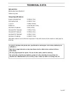
Torque Specifications

·Engine crankshaft bolt 

50 ft/lb (67 Nm)

·Deck pulley bolts 

45 ft/lb (61 Nm)

·Lug nuts 

75 ft/lb (100 Nm)

·Blade bolt 

45-55 ft/lb (60-75 Nm)

·Standard ¼” fasteners 

9 ft/lb (12 Nm)

·Standard 5/16” fasteners 

18 ft/lb (25 Nm)

·Standard 3/8” fasteners 

33 ft/lb (44 Nm)

·Standard 7/16” fasteners 

52 ft/lb (70 Nm)

·Standard ½” fasteners 

80 ft/lb (110 Nm)

When this product is worn out and no longer used, it should be returned to the reseller or other party for 
recycling.

In order to implement improvements, specifications and designs can be altered without prior 
notification.

Note that no legal demands can be placed based on the information contained in these 
instructions.

Use only original parts for repairs. The use of other parts voids the warranty.

Do not modify or install non-standard equipment to the unit without consent from the 
manufacturer. Modifications to the unit may cause unsafe operations or damage the unit.

Summary of Contents for 968999633

Page 1: ...he frame receiver d Install the 1 2C centerlock nuts finger tight to the side post bolts 3 Install roll bar top loop a Align the holes of the top loop with the left and right side posts b Slide the latch pins through the front hole on the left and right side to connect the top loop to the side posts Secure with the hairpin c Using 1 2C x 3 1 4 cap screws through the rear hole on the left and right...

Page 2: ...FIG 2 Loosen the discharge chute slightly and lower into position Chute should be snug but still pivot freely FIG 1 FIG 2 FIG 3 Discharge Chute If discharge chute is not assembled to the cutting deck follow the instructions below 1 Hook the spring end over the discharge chute and align the internal diameter of the spring with the holes in the chute 2 Align the chute and spring with the tabs on the...

Page 3: ... Set deck cutting height at 4 4 Rotate blades to align front to back 5 Measure front blade tip should be 4 from ground If not turn locknut on top of front eyebolt until measurement is achieved Check blade tip at front on opposite front blade Adjust locknut on front eyebolt as necessary 6 Check rear blade measurement should be 4 1 4 from ground If not turn locknut on top of rear eyebolt to achieve ...

Page 4: ... parking lot or open field for tracking adjustment 5 Test operate unit by driving it at full throttle and full forward position on both motion control levers Gradually turn in the tracking bolt on the right hand side until the unit noticeably starts drifting right 6 Stop the unit and tighten right jam nut in this position 7 Restart the unit and drive forward at full throttle with both motion contr...

Page 5: ...Please read the operator s manual carefully and make sure you understand the instructions before using the machine English Operator s manual RAM 44 26 B S 968999633 RAM 50 26 B S 968999634 ...

Page 6: ...intenance 35 Maintenance Schedule 35 Battery 37 Ignition System 38 Checking the Safety System 39 Checking the Engine s Cooling Air Intake 40 Checking and Adjusting the Throttle Cable 40 Checking and Adjusting the Choke Cable 40 Replacing the Air Filter 41 Replacing the Fuel Filter 43 Checking the Fuel Pump s Air Filter 43 Checking Tire Pressures 43 Checking the Parking Brake 44 Checking the V belt...

Page 7: ...o the operator or other persons The owner must understand these instructions and must allow only trained persons who understand these instructions to operate the mower Each person operating the mower must be of sound mind and body and must not be under the influence of any mind altering substance ...

Page 8: ...ble road traffic regulations before transporting on public roads If the machine is transported you must always use approved fastening equipment and ensure that the machine is well anchored DO NOT operate this machine on public roadways Towing Do not tow this machine it may cause damage to the drive system Do not tow any trailers etc with this mower They may jackknife or overturn causing damage to ...

Page 9: ...nal Manufacturing Number The machine s manufacturing number can be found on the printed plate affixed to the left in the engine compartment Stated on the plate from the top are The machine s type designation I D The manufacturer s type number Model The machine s serial number Serial no Please state the type designation and serial number when ordering spare parts The engine s manufacturing number i...

Page 10: ...there is a potential for misuse or misassembly WARNING Xxxxxxx xxxx xxxxxxxx xxx x Xxxxx xxxxxx xx xx xxxxxxxx xxxxx xxx xx IMPORTANT INFORMATION Xxxxxxx xxxx xxxxxxxx xxx xxx xxxx xxxxxx xx Parking brake Do not stand here Battery acid is corrosive explosive and flammable CE conformity marking Only for European market Warning Rotating blades keep away from the discharge deck Do not touch rotating ...

Page 11: ...not open or remove safety shields while engine is running Careful backing up watch for other people Careful going forward watch for other people Read Operator s Manual Shut off engine remove key before performing any maintenance or repair work Keep a safe distance from the machine Use on slopes no greater than 10 No passengers ...

Page 12: ...nd pets before operating Stop machine if anyone enters the area Never carry passengers The machine is only intended for use by one person Do not mow in reverse unless absolutely necessary Always look down and behind before and while backing Never direct discharged material toward anyone Avoid discharging material against a wall or obstruction Material may ricochet back toward the operator Stop the...

Page 13: ...otect themselves and others from serious injury Follow the manufacturer s recommendation for wheel weights or counterweights Never allow children or other persons not trained in the use of the machine to use or service it Local laws may regulate the age of the user Anyone who operates this machine should first read and understand this Operator s Manual Keep machine free of grass leaves or other de...

Page 14: ...uts bumps rocks or other hidden objects Uneven terrain could overturn the machine Tall grass can hide obstacles Choose a low ground speed so that you will not have to stop while on the slope Do not mow on wet grass Tires may lose traction Avoid starting stopping or turning on a slope If the tires lose traction disengage the blades and proceed slowly straight down the slope Keep all movement on the...

Page 15: ... activity Never assume that children will remain where you last saw them Keep children out of the mowing area and in the watchful care of a responsible adult other than the operator Be alert and turn machine off if a child enters the area Before and while backing look behind and down for children Never carry children even with the blades shut off They may fall off and be seriously injured or inter...

Page 16: ...If this is not possible then refuel such equipment with a portable container rather than from a gasoline dispenser nozzle Keep the nozzle in contact with the rim of the fuel tank or container opening at all times until fueling is complete Do not use a nozzle lock open device If fuel is spilled on clothing change clothing immediately Never overfill fuel tank Replace gas cap and tighten securely Do ...

Page 17: ...blades are sharp Wrap the blade or wear gloves and use extra caution when servicing them Check brake operation frequently Adjust and service as required Maintain or replace safety and instruction labels as necessary Do not modify safety equipment Check regularly to be sure it works properly The machine must not be driven with defective or unmounted protective plates protective cowlings safety swit...

Page 18: ...ve goggles Ensure that the fuel filler cap is mounted tightly and no flammable substances is stored in an open vessel Never work with the starter circuit if there is spilled fuel Disconnect the chassis cable from the battery first and reconnect it last Do not make a bridge short circuit across the starter relay to run the starter Never use the machine indoors or in spaces lacking proper ventilatio...

Page 19: ...om a vehicle or trailer Use an approved trailer to transport the machine Activate the parking brake turn off the fuel supply and fasten the machine with approved fastening devices such as bands chains or straps when transporting Do not operate this machine on public roadways Check and abide by local traffic regulations before transporting the machine on any road Do not tow this machine it may caus...

Page 20: ...rain Use yours A spark arrester for the muffler is available through your authorized Dixon dealer WARNING This mower is equipped with an internal combustion engine and should not be used on or near any unimproved forest covered bush covered or grass covered land unless the engine s exhaust system is equipped with a spark arrester meeting applicable local or state laws if any If a spark arrester is...

Page 21: ...steering controls the flow is regulated and thereby the direction and speed Control Locations Page Page 1 Parking brake 17 8 Hour meter 21 2 Motion control levers 16 9 Choke control 21 3 Fuel shut off valve 18 10 Ignition switch 21 4 Seat adjustment bolts 18 11 Throttle control 22 5 Fuel tank cap 19 12 Blade switch 22 6 By pass linkage 19 13 Cutting height pedal 23 7 Fuses 20 Zero Turn Rider 8050 ...

Page 22: ...turn right while moving forward move the right control towards the neutral position The rotation of the right wheel is reduced and the machine turns to the right Zero turn can be achieved by moving one control backward behind the neutral position and carefully moving the other steering control forward from its neutral position The rotation direction when zero turning is determined by which steerin...

Page 23: ...fuel shut off valve is located under the fuel tank The valve has two positions ON and OFF 4 Seat adjustment bolts With the machine off remove the two bolts holding the seat pan down and flip the seat forward The seat can be adjusted lengthways When making adjustments loosen the four bolts under the seat pan after which the seat can be moved backward or forward Once the seat is adjusted to your lik...

Page 24: ... INFORMATION Experience indicates that alcohol blended fuels called gasohol ethanol or methanol can attract moisture which leads to separation and formation of acids during storage Acidic gas can damage the fuel system of an engine while in storage To avoid engine problems the fuel system should be emptied before storage of 30 days or longer Drain the gas tank start the engine and let it run until...

Page 25: ...nto the slots and release so that it is held in the bypass position To reengage the IZT s to drive reverse the above procedure 7 Fuses The fuses are located in a holder at the right hand side of the battery compartment They are flat pin fuses of the same type used in automobiles There are two fuses Fuse ratings and functions 20 A Primary fuse 7 5 A Mower deck coupling CZ10 2 1 IZT Bypass linkage B...

Page 26: ...on will come on and shut off automatically The hour meter can not be manually reset 9 Choke Control The choke control is used for cold starts in order to provide the engine with a richer fuel mixture For cold starts the control should be pulled out 10 Ignition Switch The ignition key is placed on the control panel and is used to start and stop the engine 8050 147 Hour meter 8050 148 Choke control ...

Page 27: ...pectively Avoid idling the engine for long periods as there is a risk of fouling the spark plugs USE FULL THROTTLE WHEN MOWING for best mower performance and battery charging 12 Blade switch In order to engage the mower deck pull the knob out the mower blades are disengaged when the knob is depressed IMPORTANT INFORMATION Do not run the starter for more than five seconds each time If the engine do...

Page 28: ...ements The heights are measured from the ground up to the blade tip with the engine not running To change cutting heights move the pin on the cutting height plates to the desired height of cut Accessories For mulching there is a BioClip attachment available This is mounted underneath the mower deck and consists of control plates and BioClip blades 1 Foot pedal 2 Lift arm 3 Height plate Cutting hei...

Page 29: ...e operator must be in the seat start engine see Before Starting in Operation section adjust engine speed to idle disengage park brake do not engage blades at this time rotate control levers inward As long as the control levers have not been moved forward or backwards mower will not move Slowly move both control levers forward slightly this will allow mower to start moving forward in a straight lin...

Page 30: ...he engine can be started the driver must be seated on the seat the blade switch for engaging the mower blades must be depressed the parking brake must be on use the personal safety equipment described in the safety instruction section both steering controls must be in the locked outer neutral position Starting the Engine 1 Sit on the seat 2 Raise the mower deck by depressing the pedal forward to t...

Page 31: ...switch 5 Move the steering controls outward to the locked outer neutral position 6 Move the throttle to the middle position 8011 668 Depress the control for disengaging the mower deck 8011 724 Steering controls in the outward locked neutral position 8050 150 Set the throttle ...

Page 32: ... the choke control should be pulled out to its extents 8 Open the fuel shut off valve 9 Press in and turn the ignition key to the start position 8050 148 Set the choke control CZ15 Open the fuel shut off valve 8050 153 Turn to the start position ...

Page 33: ...EN MOWING 8050 154 Return to run position IMPORTANT INFORMATION Do not run the starter for more than 10 seconds each time If the engine does not start wait about 60 seconds before re trying 8050 148 Gradually slide the choke control 8050 150 Set the engine speed WARNING Engine exhaust and certain vehicle components contain or emit chemicals considered to cause cancer birth defects or other reprodu...

Page 34: ...ood CHASSIS GROUND on the mower with the discharged battery away from the fuel tank and battery To remove cables reverse order Remove BLACK cable first from chassis and then from the fully charged battery Remove RED cable last from both batteries WARNING Lead acid batteries generate explosive gases Keep sparks flame and smoking materials away from batteries Always wear eye protection when around b...

Page 35: ...from objects that could be thrown by the rotating blades 5 Engage the mower deck by pulling out the blade switch 6 Move throttle control to full throttle 7 The machine s speed and direction are continuously variable using the two steering controls When both controls are in the neutral position the machine stands still By moving both controls an equal amount forward or backward the machine moves in...

Page 36: ... be used before starting up or down hills Avoid stopping or changing speed on hills If stopping is absolutely necessary pull drive levers into the neutral position and push to the outside of the unit and engage the park brake To restart movement release the park brake Pull the control levers back to the center of the mower and press forward to regain forward motion Make all turns slowly WARNING To...

Page 37: ...ecomes more even and the grass clippings more evenly distributed over the mown area The total time taken is not increased as a higher operating speed can be used without poor mowing results Avoid mowing wet lawns The mowing result is poorer because the wheels sink into the soft lawn clumps build and the grass clippings fasten under the cowling Hose the mower deck underside with water after each us...

Page 38: ...ition 3 When the machine is standing still activate the parking brake by pulling the lever backward 4 Move the throttle to the minimum position tortoise symbol Turn the ignition key to the stop position Never use choke to stop engine 5 Move the steering controls outward 6 Remove key Always remove key when leaving the mower to prevent unauthorized use 8011 668 Disengage the mower deck 8011 718 2 Ra...

Page 39: ...est cutting position Pull the IZT bypass linkages out and into the slots and release so that it is held in the bypass position To reengage the IZT s to drive reverse the above procedure WARNING No adjustments or maintance to be carried out unless the engine stopped the ignition key has been removed the parking brake is on CZ10 2 1 IZT Bypass linkage Bypass linkages CZ12 1 Head outside of rear deck...

Page 40: ... in this manual Not described in this manual Daily mainte nance Weekly mainte nance At least once each year Maintenance interval in hours Maintenance Page Before After 25 50 100 300 Check the parking brake 53 z Check the engine s oil level every refueling 57 z Check the safety system 39 z Check for fuel and oil leakages Check clean the engine s cooling air intake 40 z Check the mower deck 47 z Che...

Page 41: ... filter 58 z z Clean replace the spark plugs 38 z z Replace the fuel filter 44 z z Replace the air filter paper filter 2 43 z z Check the caster wheels every 200 hours 51 z Clean the cooling fins 2 Replace the air cleaner s pre filter 2 foam 41 z z Check adjust the mower deck 49 z z Check the engine valve clearance4 Perform the 300 hour service 4 79 Lubricate according to Lubrication Schedule 54 z...

Page 42: ...ate forward 2 Open terminal access doors 3 Using two 1 2 wrenches disconnect BLACK battery cable then RED battery cable 4 Using 7 16 wrench remove terminal guard 5 Carefully remove the battery from the mower 6 Install new battery with terminals in the same position as the old battery 7 Reinstall terminal guard 8 First connect RED battery cable to positive battery terminal with hex bolt and hex nut...

Page 43: ...he spark plug with a steel brush if it is to be reused 4 Measure the electrode gap with a gapping tool The gap should be 030 0 75 mm Adjust as necessary by bending the side electrode 5 Reinsert the spark plug turning by hand to avoid damaging the threads 6 After the spark plug is seated tighten it using a spark plug wrench so that the washer is compressed A used spark plug should be turned 1 8 of ...

Page 44: ...f the conditions is not met Change the conditions and try again If the machine starts when one of these conditions is not met turn the machine off and repair the safety system before using the machine again Make sure the engine stops when the park brake is not engaged and the operator leaves the seated position Check that the engine stops if the mower blades are engaged and the driver temporarily ...

Page 45: ...2 Check that the throttle cable is mounted in the correct hole in the lower lever see illustration 3 Push the throttle cable s outer casing as far to the right as possible and tighten the clamping screw Checking and Adjusting the Choke Cable If the engine produces black smoke or is difficult to start this can be because the choke cable is incorrectly adjusted upper cable If doubts arise contact th...

Page 46: ...rate with engine oil and squeeze it inside a clean absorbenth cloth 4 Tap the paper filter against a fixed surface to remove dust If the paper filter is still dirty it must be replaced 5 Wipe clean the inside of air filter housing 6 Refit the foam filter pre filter 7 Mount the filter in the air filter housing 8 Replace the cowling over the air filter housing WARNING The engine and the exhaust syst...

Page 47: ...t the air filter as follows Check that the seal on the bottom of the paper filter is whole Mount the safety element in the air filter housing 5 Place the paper filter over the safety element 6 Replace the cover over the air filter housing Fasten the two metal clamps making sure the cover is snapped into position 7 Push top of dust load indicator to reset it IMPORTANT INFORMATION Do not use compres...

Page 48: ... pointing up toward the fuel pump If necessary a soap solution can be applied to the filter ends to ease mounting 4 Move the hose clamps back toward the filter Checking the Fuel Pump s Air Filter Regularly check that the fuel pump s air filter is free from dirt Remove the screws and open the pump no hoses need be removed The filter can be cleaned with a brush if necessary Replace the filter on the...

Page 49: ...el surface Apply park brake Lower the deck into the lowest cutting position Using a ratchet with a 9 16 socket on the spring idler bolt to relieve the tension on the belt Remove screws from both the left and right belt shields and remove shields Remove any dirt or grass that may have accumulated around the cutter housings and entire deck surface Carefully roll the belt over the top of the cutter h...

Page 50: ...eck wrap the belt around the large right side idler right cutter housing pulley small center idler center pulley left side pulley and then around the large left side idler The belt will be loose at this point Using a ratchet with a 9 16 socket on the spring idler bolt to relieve the tension on the belt See decal on the top of deck for belt routing information After installation is complete check t...

Page 51: ...tension The belt should now be able to be removed from the engine pulley and IZT pulleys Belt installation Wrap the IZT belt around the IZT pulleys Route the belt around the inside of the idler pulley Now you can wrap the belt around the engine pulley Reattach the spring on the pump idler arm if previously disconnected Reinstall the deck belt onto the electric clutch pulley see to replace deck bel...

Page 52: ...de whether the blade can be repaired ground or must be replaced Balance the blades after sharpening Check the blade mounts Damaged blades should be replaced when hitting obstacles that result in a breakdown Let the service workshop decide whether the blade can be repaired ground or must be replaced 8011 604 Check the blades WARNING Blades are sharp Protect your hands with gloves and or wrap blades...

Page 53: ... 45 55 ft lbs 60 75 Nm WARNING Blades are sharp Protect your hands with gloves and or wrap blades with a heavy cloth when handling IMPORTANT INFORMATION To ensure proper assembly center hole in blade must align with star on cutter housing 8011 671 1 Blade 2 Center hole 3 Star 4 Cutter housing 5 Blade bolt special Blade attachment principal IMPORTANT INFORMATION Special blade bolt is heat treated R...

Page 54: ...are equally tensioned If they are not adjust the appropriate lower chain bolt in its slot Adjusting Cutting Height 1 Raise and secure the deck height lever to the transport position 4 1 2 2 Position blade tip so it is straight forward 3 Measure from the cutting edge of the blades to a flat level surface The distance should be 4 1 2 114 mm 4 Drop and secure the lever at for example the 2 cutting he...

Page 55: ...ction of this manual 2 Using a 3 4 wrench and a 9 16 wrench remove the nut and shoulder bolt from the anti scalp roller 3 Lower the anti scalp roller to the ground and raise it up to the next highest hole 4 Replace and tighten the nut and shoulder bolt 5 Be sure to adjust all of the anti scalp rollers to the same position 6 Be sure to readjust the anti scalp rollers if the cutting height is change...

Page 56: ... before washing Caster Wheels Check every 200 hours Check that wheels rotates freely If wheels do not rotate freely take the unit to your dealer for service Foam filled tires or solid tires will void the warranty Removal and installation of caster wheel 1 Remove nut and caster bolt 2 Pull the wheel out of the fork and take care of the sleeve 3 Install in reverse order Tighten caster bolt Hardware ...

Page 57: ... pin and brake rod washer Repeat the procedure on the other IZT Tracking adjustment If the mower is not tracking straight check the air pressure in both rear tires Recommended air pressure is 15 psi 1 bar If the unit will not track straight follow the steps below Tracking must be checked on a flat and level concrete or blacktop surface Mower is tracking to the right Increase the air pressure 2 3 p...

Page 58: ...be lubricated twice weekly Wipe away excess grease after lubrication It is important to avoid getting lubricant on the belts or the drive surfaces on the belt pulleys Should this happen attempt to clean them with spirits If the belt continues to slip after cleaning it must be replaced Gasoline or other petroleum products must not be used to clean belts 7 8011 672 3 Lubricate with grease gun Oil ch...

Page 59: ...ricating in Accordance with the Lubrication Schedule 1 Front Wheel Mount Lubricate with a grease gun one zerk for each wheel mount until the grease is forced out Use only good quality bearing grease Grease from well known brand names petrochemical companies etc usually maintains a good quality 2 Front Wheel Bearings Lubricate with a grease gun one zerk for each set of wheel bearings until the grea...

Page 60: ...he oil to run out into the container 5 Then close the oil drain valve 6 Replace the oil filter if necessary 7 Fill with new engine oil in accordance with Checking the Oil Level 8 Start the engine Run it for a few seconds Stop and re check the oil level 8011 733 Deck outer spindle WARNING Engine oil can be very hot if it is drained directly after stopping the engine Allow the engine to cool somewha...

Page 61: ... is approaching the ADD mark fill the oil to the FULL mark on the dipstick Never fill to above the FULL mark The oil is filled through the hole for the dipstick API class SF SG SH SJ or higher must be used Syntetic oil SAE 5W 30 or 10W 30 is recommended at all temperatures Mineral oil SAE 5W 30 10W 30 can be used between 18 C 0 F and 5 C 40 F At temperature above 5 C 40 F single grade SAE 30 must ...

Page 62: ...lowing procedure can be performed with the transaxles installed in the vehicle and the vehicle on level ground Apply the bypass valve for each transaxle and lock the vehicle parking brake 1 Remove the three 1 4 filter guard screws and filter guard Clean any loose debris from around the perimeter of the filter See illustrations 2 Place an oil drain pan 12 or more diameter and 8 qt capacity is optim...

Page 63: ... oil until oil just appears at the bottom of each transaxles top port approximately 2 quarts per transaxle 4 quarts total Install the top port lug into each transaxle as the oil level reaches this port 11 Install and torque the top port plugs to 180 in lbs 12 Continue to fill the transaxles through the expansion tank until the Full Cold line is reached this will take approximately 23 additional ou...

Page 64: ... drive wheels off the ground Then repeated under normal operating conditions 1 Disengage the brake if activated 2 With the bypass valve open and the engine running at fast idle slowly move the directional control in both forward and reverse directions 5 or 6 times As air is purged from the unit the oil level will drop 3 With the bypass valve closed and the engine running slowly move the directiona...

Page 65: ...ts on the battery terminal cable connections Fuse blown Ignition system faulty Fault in the starter safety circuit See Checking the Safety System in the Maintenance Section The engine runs rough Faulty carburetor The choke control is pulled out with a warm engine Defective valves Defective piston cylinder piston ring or cylinder head seal The cylinder head bolts are loose Clogged fuel filter or je...

Page 66: ...tion incorrect Air trapped in hydraulic system Battery not charging Poor contact with battery terminal cable connectors The machine moves slowly unevenly Parking brake on or not at all Bypass valve on pump open Drive belt for the transmission gears slack or has come off Air trapped in hydraulic system Mower deck not engaging Drive belt for the mower deck has come loose Contact for the electromagne...

Page 67: ...and right sides Bent blades The suspending for the mower deck is uneven The chain fixture has come loose The blades are blunt Driving speed too high The grass is too long Grass collected under the mower deck The machine vibrates The blades are loose The blades are incorrectly balanced The engine is loose ...

Page 68: ...y 4 Empty the fuel tanks or add a fuel stabilizer Start the engine and allow it to run until the carburetor is drained of fuel or the stabilizer has reached the carburetor 5 Remove the spark plug and pour about a tablespoon of engine oil into the cylinder Turn over the engine so that the oil is evenly distributed and then refit the spark plug 6 Lubricate all grease zerks joints and axles 7 Remove ...

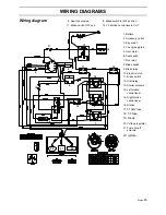
Page 69: ...ch 7 Run relay 8 Blade switch 9 Brake relay 10 Electric clutch 11 Brake switch 12 Start relay 13 Starter solenoid 14 Left motion control lever 15 Right motion control lever 16 Starter 17 20 AMP fuse 18 7 5 fuse 19 Diode 20 Voltage regulator 21 Fuel shut off solenoid 22 Ignition 6 Seat unoccupied 8 Blade switch in OFF position 11 Brake switch OFF pos 14 15 Motion control levers OUT ...

Page 70: ...5 Min 86 octane unleaded Max methanol 5 max eth anol 10 Max MTBE 15 Fuel tank capacity 5 gallon 5 gallon Spark plugs gap NGK BPR4ES 030 0 75 mm NGK BPR4ES 030 0 75 mm Cooling Air cooling Air cooling Air filter Standard Standard Alternator 12 V 16 A 12 V 16 A Starter Electric 12 V Electric 12 V Transmission Transmission ZT2800 Hydo Gear ZT2800 Hydo Gear Speed and direction controls Dual levers foam...

Page 71: ...ion 11 gauge w 10 gauge skirts 11 gauge w 10 gauge skirts Productivity Productivity Overall dimensions Weight 625lbs 283 kg 605lbs 274 kg Base machine length 69 1 2 177 cm 72 183 cm Base machine width 44 112 cm 50 127 cm Base machine height 40 102 cm 40 102 cm Overall width Chute up Overall width Chute down Vibration Daily Exposure Hand Arm A 8 2 44 m s2 2 20 m s2 Whole Body A 8 0 23 m s2 0 14 m s...

Page 72: ... fasteners 80 ft lb 110 Nm When this product is worn out and no longer used it should be returned to the reseller or other party for recycling In order to implement improvements specifications and designs can be altered without prior notification Note that no legal demands can be placed based on the information contained in these instructions Use only original parts for repairs The use of other pa...

Page 73: ...pecial requirements for any of the states Californian emission rules etc Do not remove any of these labels Certificates can also be supplied with the machine at delivery or written in the Engine manual Take care of them as they are valuable documents CE requirements Vibration data corresponding to Directive 2002 44 EC is given in the Technical Data Section The Declaration of Conformity is included...

Page 74: ...ment 11 Check The safety switch for the parking brake The safety switch for the mower deck The safety switch in the seat The safety switch in the steering controls Parking brake functionality Driving forward Driving backward Engaging the blades 12 Check the idle speed 13 Check the engine high idle speed 14 Inform the customer about The need and advantages of following the service schedule The need...

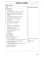
Page 75: ...English 70 SERVICE JOURNAL After the First 5 8 Hours 1 Change engine oil ...

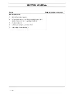
Page 76: ...Service 1 Check the fuel pump s air filter 2 Sharpen Replace mower blades if required 3 Check the tire pressures 4 Check battery with cables 5 Lubricate according to lubrication chart 6 Check clean the engine s cooling air intake 7 Clean the air cleaner s pre filter foam ...

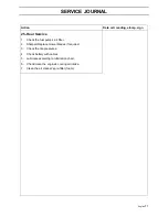
Page 77: ...sign 50 Hour Service 1 Perform the 25 hour service 2 Clean replace the air cleaner s filter cartridge paper filter shorter intervals for dusty operating conditions 3 Change engine oil 4 Lubricate according to lubrication chart 5 Check adjust the parking brake ...

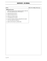
Page 78: ...ur service 2 Perform the 50 hour service 3 Change the engine oil filter 4 Clean replace the spark plugs 5 Replace the fuel filter 6 Clean the cooling fins on the engine and transmission 7 Check V belts 8 Check tighten caster wheel axle bolts every 200 hours 9 Change the air filter s paper cartridge ...

Page 79: ...ith the customer as to which additional work is to be carried out 2 Perform the 25 hour service 3 Perform the 50 hour service 4 Perform the 100 hour service 5 Check adjust the mower deck 6 Clean the combustion chamber and grind the valve seats 7 Check the engine valve clearance 8 Replace the air cleaner s pre filter foam ...

Page 80: ...e the air filter s paper cartridge 4 Change the engine oil 50 hours 5 Replace the engine oil filter 100 hours 6 Check adjust the cutting height 7 Check adjust the parking brake 50 hours 8 Clean Change the spark plugs 100 hours 9 Change the fuel filter 100 hours 10 Clean the cooling fins 100 hours 11 Check the engine valve clearance 12 Perform the 300 hour service at an authorized service workshop ...

Page 81: ...English 76 SERVICE JOURNAL Action Date mtr reading stamp sign ...

Reviews: