background image

17

V-BELTS

Check V-belts for deterioration and wear after 100 hours 

of operation and replace if necessary. The belts are not 

ad just able. Re place belts if they begin to slip from wear.

TRANSAXLE COOLING

The transmission fan and cooling fins should be kept clean 

to assure proper cooling.
Do not attempt to clean fan or transmission while engine 

is running or while the transmission is hot. To prevent pos-

 si ble damage to seals, do not use high pressure water or 

steam to clean transaxle.
• 

Inspect cooling fan to be sure fan blades are intact and 

clean.

•  Inspect cooling fins for dirt, grass clippings and other 

materials. To prevent damage to seals, do not use com-

pressed air or high pressure sprayer to clean cooling fins.

TRANSAXLE PUMP FLUID 

The transaxle was sealed at the factory and fluid main te-

 nance is not required for the life of the transaxle.  Should 

the transaxle ever leak or require servicing, contact your 

near est au tho rized ser vice center/department.

MAINTENANCE

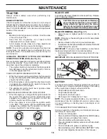
Fig. 18

TEMPERATURE RANGE ANTICIPATED BEFORE NEXT OIL CHANGE

SAE VISCOSITY GRADES

-20 0 30 40 

80 

100 

-30 

-20 0  20 30 

40 


F


C

32 

-10 

10 

60 

5W-30

10W30

ENGINE

LUBRICATION

Only use high quality detergent oil rated with API service 

classification SG-SL.   Select the oil’s SAE viscosity grade 

according to your expected operating temperature.

Change the oil after every 50 hours of operation or at least 

once a year if the tractor is not used for 50 hours in one year.
Check the crankcase oil level before starting the engine 

and after each eight (8) hours of operation.    

TO CHANGE ENGINE OIL (See Fig. 18 & 19) 

Determine temperature range expected before oil change.  

All oil must meet API service classification SG-SL.
•  Ensure tractor is on level surface.
•  Oil will drain more freely when warm.
•  Catch oil in a suitable container.
• 

Remove oil fill cap/dipstick.  Be careful not to allow dirt 

to enter the engine when changing oil.

• 

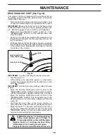
Slide oil drain extension under oil drain hole (drain hole 

may be flush with or protrude from engine block side wall).

• 

Make sure back face of oil drain extension is flush with 

engine side wall.

•  Make sure bottom lip of oil drain extension is lined up 

with bottom of oil drain hole.

• 

Position a container to catch oil directly under front end 

of oil drain extension.

• 

Slide a 1/2” (12 point) socket mounted on an extension 

onto oil drain plug.

• 

Loosen plug while holding the oil drain extension firmly 

in place.

•  Drain oil into container.
• 

After oil has drained completely, reinstall oil drain plug.  

(Do not tighten more than 13 Ft. Lbs./17 Nm)

•  Refill engine with oil through oil fill dipstick tube.  Pour 

slowly.  Do not overfill.  For approximate capacity see 

“PRODUCT SPECIFICATIONS” section of this man u al.

•  Use gauge on oil fill cap/dipstick for checking level.  

Ensure dipstick cap is tightened securely for accurate 

reading.  Keep oil at “FULL” line on dipstick. Tighten 

cap onto the tube securely when finished.

Fig. 19

OIL DRAIN HOLE

OIL DRAIN 

EXTENSION

OIL DRAIN PLUG

CAUTION: If engine has been operated 

for an extended period of time immedi-

ately prior to draining oil, oil will be hot.

ENGINE OIL FILTER

Replace the engine oil filter every season or every other 

oil change if the tractor is used more than 100 hours in 

one year.

Summary of Contents for D15KH30

Page 1: ...tor s Manual D15KH30 03131 581 27 03 27 Rev 5 Gasoline containing up to 10 ethanol E10 is acceptable for use in this machine The use of any gasoline exceeding 10 ethanol E10 will void the product warr...

Page 2: ...ook down and behind before and while backing Never direct discharged material toward anyone Avoid dischargingmaterialagainstawallorobstruction Material may ricochet back toward the operator Stop the b...

Page 3: ...OF GASOLINE To avoid personal injury or property damage use extreme care in handling gasoline Gasoline is extremely flammable and the vapors are explosive Extinguish all cigarettes cigars pipes and o...

Page 4: ...hni cians and the proper tools to service or repair this tractor Please read and retain this manual The instructions will enable you to assemble and maintain your tractor properly Always observe the S...

Page 5: ...inthe ServiceandAdjustments section in this manual Fig 1 LABEL TOOLS REQUIRED FOR ASSEMBLY A socket wrench set will make assembly easier Standard wrench sizes are listed 1 5 16 wrench Utility knife 2...

Page 6: ...ENT HANDLE Fig 3 Fig 4 NOTE You may now roll your tractor off the skid Follow the instructions below to remove the tractor from the skid WARNING Beforestarting read understandandfollow all instruction...

Page 7: ...Become familiar with all controls their location and function Operate them before you start the engine Be sure brake system is in safe operating condition Be sure Operator Presence System and Reverse...

Page 8: ...ty damage DANGER indicates a hazard which if not avoided will result in death or serious injury WARNING indicates a hazard which if not avoided could result in death or serious injury CAUTION indicate...

Page 9: ...ting the engine C PARKING BRAKE Locks clutch brake pedal into the brake position D THROTTLE CHOKE CONTROL Used for starting and controlling engine speed E ATTACHMENT CLUTCH LEVER Used to engage the mo...

Page 10: ...g brake will hold tractor secure Fig 7 B C Fig 6 STOPPING See Fig 7 MOWER BLADES To stop mower blades place attachment clutch control in the DISENGAGED position GROUND DRIVE To stop ground drive depre...

Page 11: ...eels are properly adjusted when they are slightly off the ground when mower is at the desired cutting height in operating position Gauge wheels then keep the deck in proper position to help prevent sc...

Page 12: ...ON POSITION NORMAL OPERATING 02828 Fig 13 OPERATION REVERSE OPERATION SYSTEM ROS Your tractor is equipped with a Reverse Operation System ROS Any attempt by the operator to travel in the reverse direc...

Page 13: ...e extra cranking time to move fuel from the tank to the engine Ensurefreewheelcontrolisinthetransmissionengaged position Sit on seat in operating position depress brake pedal and set parking brake Mov...

Page 14: ...er engage or disengage free wheel lever while the engine is running To ensure proper operation and performance it is recom mended that the transmission be purged before operating tractor for the first...

Page 15: ...Check Replace Mower Blades Che Clean Debris Off Steering Plate ck Transaxle Cooling Che Check Operator Presence ROS Systems ck V Belts Check Mower Levelness LUBRICATION CHART GENERAL RECOMMENDATIONS T...

Page 16: ...s running with the ignition switch in the ROS ON position and the attachment clutch engaged any attempt by the operator to shift into reverse should NOT shut off the engine BLADE CARE Forbestresultsmo...

Page 17: ...after each eight 8 hours of operation TO CHANGE ENGINE OIL See Fig 18 19 Determine temperature range expected before oil change All oil must meet API service classification SG SL Ensure tractor is on...

Page 18: ...e cooling shrouds are reinstalled NOTE Operating the engine with a blocked grass screen dirtyorpluggedcoolingfins and orcoolingshroudsremoved will cause engine damage due to overheating CLEAN AIR SCRE...

Page 19: ...on Pull back the lock collar of the hose connector and push the connector onto the deck washout port at the left end of the mower deck Release the lock collar to lock the connector on the nozzle IMPOR...

Page 20: ...from chassis pin B and rear lift link C from rear mower bracket D remove retainer springs and washers CAUTION AFTER REAR LIFT LINKS ARE DISCONNECTED THE ATTACH MENT LIFT LEVER WILL BE SPRING LOADED H...

Page 21: ...nd secure with retainer spring Repeat on opposite side of tractor ATTACH REAR LIFT LINKS C Lift rear corner of mower and position slot in link assembly over pin D on rear mower bracket and secure with...

Page 22: ...t your adjustment by mowing some uncut grass and visually checking the appearance Readjust if neces sary until you are satisfied with the results PRECISION SIDE TO SIDE ADJUSTMENT See Fig 30 With all...

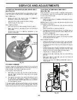
Page 23: ...oves and inside all belt guides and keepers Install mower See TO INSTALL MOWER section in this manual Fig 34 02952 A B C D E F G SERVICE AND ADJUSTMENTS Fig 33 TO REPLACE MOWER BLADE DRIVE BELT See Fi...

Page 24: ...l C of fully charged battery Connect the other end of the BLACK cable D to good chassis ground away from fuel tank and battery TO REMOVE CABLES REVERSE ORDER BLACK cable first from chassis and then fr...

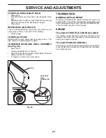
Page 25: ...r Stand in front of tractor Grasp hood at sides tilt toward engine and lift off of tractor To replace reverse above procedure Fig 38 TRANSMISSION REMOVAL REPLACEMENT Should your transmission require r...

Page 26: ...Plastic cannot breathe which allows condensation to form and will cause your tractor to rust IMPORTANT NEVER COVER TRACTOR WHILE ENGINE AND EXHAUST AREAS ARE STILL WARM Immediately prepare your tracto...

Page 27: ...eck replace ignition switch 8 Faulty solenoid or starter 8 Check replace solenoid or starter 9 Faulty operator presence switch es 9 Contact an authorized service center department Engine clicks but wi...

Page 28: ...mower drive belt 9 Blades improperly installed 9 Reinstall blades sharp edge down 10 Improper blades used 10 Replace with blades listed in parts manual 11 Cloggedmowerdeckventholesfrombuildup of gras...

Page 29: ...29 SERVICE NOTES...

Page 30: ...30 SERVICE NOTES...

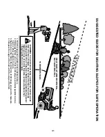
Page 31: ...never across the face Do not mow slopes greater than 15 degrees Make turns gradually to prevent tipping or loss of control Exercise extreme caution when changing direction on slopes 1 Fold this page a...

Page 32: ...05 06 14 BD Printed in the U S A...

Reviews: