background image

11

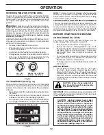
Fig. 12

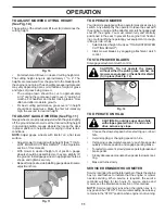
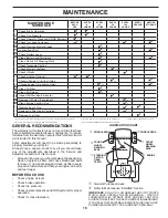
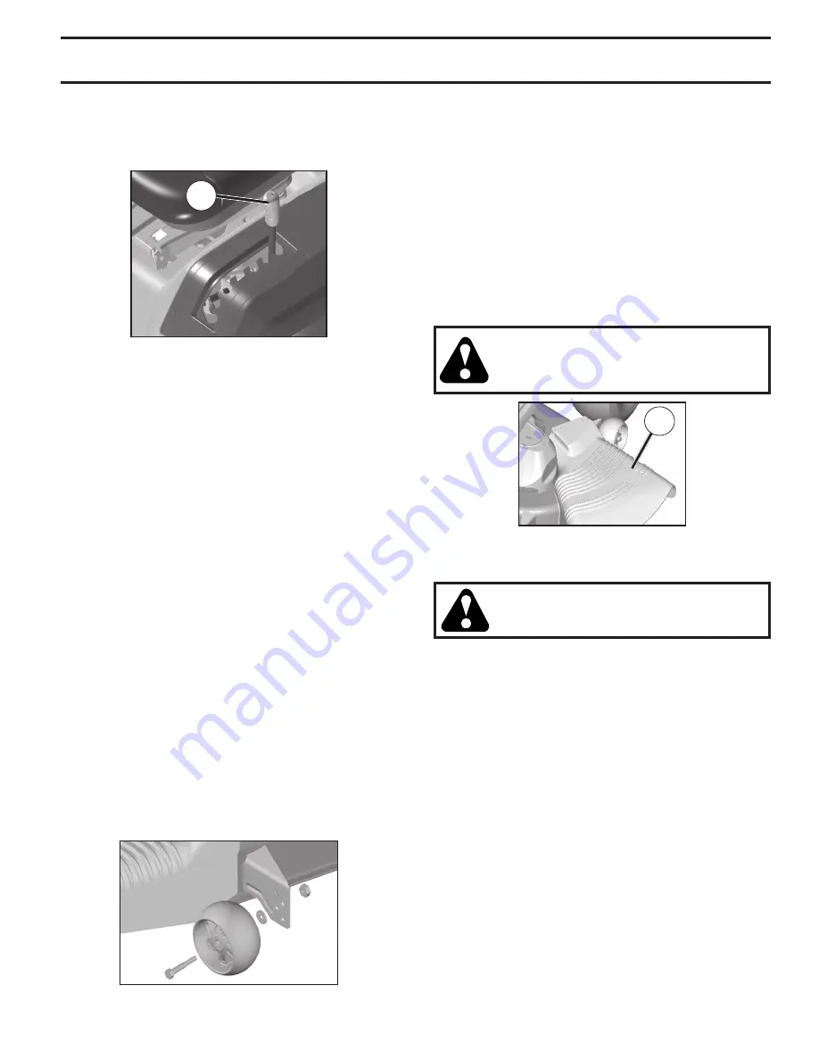
TO ADJUST MOWER CUTTING HEIGHT 

(See Fig. 10)

The position of the attachment lift lever (A) determines the 

cutting height.

•  Put attachment lift lever in desired cutting height slot.
The cutting height range is ap prox i mate ly 1" to 4". The 

heights are measured from the ground to the blade tip with 

the engine not running. These heights are approximate and 

may vary depending upon soil conditions, height of grass 

and types of grass being mowed.
•  The average lawn should be cut to approximately 

2-1/2" during the cool season and to over 3" during hot 

months. For healthier and better looking lawns, mow 

often and after moderate growth.

•  For best cutting performance, grass over 6" in height 

should be mowed twice. Make the first cut relatively 

high; the second to de sired height.

A

Fig. 10

TO OPERATE MOWER

Your tractor is equipped with an operator presence sensing 

switch.  Any attempt by the operator to leave the seat with 

the engine running and the attachment clutch engaged will 

shut off the engine. You must remain fully and centrally 

positioned in the seat to prevent the engine from hesitat-

ing or cutting off when operating your equipment on rough, 

rolling terrain or hills.
• 

Select desired height of cut (see "TO ADJUST MOWER 

CUTTING HEIGHT")

•  Start mower blades by engaging at tach ment clutch 

control.

CAUTION:  Do not operate the mower 

without either the en tire grass catcher, on 

mowers so equipped, or the deflector shield 

(S) in place (See Fig. 12).

TO STOP MOWER BLADES

Disengage at tach ment clutch con trol.

S

OPERATION

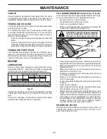
TO ADJUST GAUGE WHEELS (See Fig. 11)

Gauge wheels  are properly adjusted when they are slightly 

off the ground when mower is at the desired cutting height 

in operating position. Gauge wheels then keep the deck 

in proper position to help prevent scalping in most terrain 

conditions. 

NOTE:

Adjust gauge wheels with tractor on a flat level 

surface.
•  Adjust mower to desired cutting height (See “TO AD-

 JUST MOWER CUT TING HEIGHT” in the Operation 

sec tion of this manual).

•  With mower in desired height of cut po si tion, gauge 

wheels should be assembled so they are slightly off 

the ground. In stall gauge wheel in appropriate hole as 

shown and tighten se cure ly.

• 

Repeat for opposite side installing gauge wheel in same 

adjustment hole.

SERVICE REMINDER/HOUR METER

Service reminder shows the total number of hours the engine 

has run and flashes to indicate that the engine or mower 

needs servicing. When service is required, the service 

reminder will flash for two hours. To service engine and 

mower, see the Maintenance section of this manual.

NOTE

: Service reminder runs when the ignition key is in 

any position but "STOP". For accurate reading, be sure key 

remains in the "STOP" position when engine is not running. 

Fig. 11

TO OPERATE ON HILLS 

CAUTION: Do not drive up or down hills 

with slopes greater than 15° and do not 

drive across any slope.

•  Choose the slowest speed before starting up or down 

hills.

•  Avoid stopping or changing speed on hills.
•  If stopping is absolutely necessary, push brake pedal 

quickly to brake position and engage parking brake.

• 

To restart movement, slowly release parking brake and 

brake pedal.

• 

Slowly depress appropriate drive pedal to slowest set-

 ting.

•  Make all turns slowly.

Summary of Contents for D19KH42

Page 1: ...tor s Manual D19KH42 03131 532 44 47 85 Rev 1 Gasoline containing up to 10 ethanol E10 is acceptable for use in this machine The use of any gasoline exceeding 10 ethanol E10 will void the product warr...

Page 2: ...recommended by and comply with specificationsofthemanufacturerofyour tractor Usecommonsensewhentowing Operateonlyatthelowestpossiblespeed when on a slope Too heavy of a load while on a slope is dange...

Page 3: ...g Do not attach towed equipment except at the hitch point Follow the manufacturer s recommendation for weight limits for towed equipment and towing on slopes Neverallowchildrenorothersinorontowedequip...

Page 4: ...ow a regular schedule in maintaining caring for and using your tractor Follow the instructions under Maintenance and Stor age sections of this manual WARNING This tractor is equipped with an internal...

Page 5: ...RY inthe ServiceandAdjustments section in this manual Fig 1 LABEL Washer Hex Bolt Seat Steering Wheel Steering Wheel Adapter Steering Boot Washer Insert Hex Bolt Lock Washer Steering Extension Shaft S...

Page 6: ...ENT HANDLE Fig 3 Fig 4 NOTE You may now roll your tractor off the skid Follow the instructions below to remove the tractor from the skid WARNING Beforestarting read understandandfollow all instruction...

Page 7: ...Become familiar with all controls their location and function Operate them before you start the engine Be sure brake system is in safe operating condition Be sure Operator Presence System and Reverse...

Page 8: ...ntify safety inform ation about hazards which can result in death serious injury and or property damage DANGER indicates a hazard which if not avoided will result in death or serious injury WARNING in...

Page 9: ...brake pedal into the brake position D THROTTLE CHOKE CONTROL Used for starting and controlling engine speed E ATTACHMENT CLUTCH LEVER Used to engage the mowerblades orotherattachmentsmountedtoyourtra...

Page 10: ...NGAGED position GROUND DRIVE To stop ground drive depress brake pedal into full BRAKE position IMPORTANT FORWARD AND REVERSE DRIVE PEDALS RETURN TO NEUTRAL POSITION WHEN NOT DEPRESSED ENGINE Move thro...

Page 11: ...control S OPERATION TO ADJUST GAUGE WHEELS See Fig 11 Gauge wheels are properly adjusted when they are slightly off the ground when mower is at the desired cutting height in operating position Gauge w...

Page 12: ...hipped from the factory already filled with summer weight oil Check engine oil with tractor on level ground Pull up and remove oil fill cap dipstick wipe oil off Reinsert the dipstick into the tube an...

Page 13: ...d Theattachmentscanalsobeusedduringtheenginewarm up period after the transmission has been warmed up NOTE If at a high altitude above 3000 feet or in cold temperatures below 32 F 0 C the carburetor fu...

Page 14: ...veways etc After one or two rounds mow in the opposite direction making left hand turns until finished See Fig 15 Fig 15 If grass is extremely tall it should be mowed twice to reduce load and possible...

Page 15: ...eplace Mower Blades Che Clean Debris Off Steering Plate ck Transaxle Cooling Che Check Operator Presence ROS Systems ck V Belts Check Mower Levelness LUBRICATION CHART GENERAL RECOMMENDATIONS The warr...

Page 16: ...the ignition switch in the ROS ON position and the attachment clutch engaged any attempt by the operator to shift into reverse should NOT shut off the engine BLADE CARE Forbestresultsmowerbladesmustb...

Page 17: ...30 oil_visc_chart4_e MAINTENANCE ENGINE OIL FILTER Replace the engine oil filter every season or every other oil change if the tractor is used more than 100 hours in one year See engine manual TO CHAN...

Page 18: ...tractor unless the engine and trans mission are covered to keep water out Water in engine or transmission will shorten the useful life of your tractor Use compressed air or a leaf blower to remove gra...

Page 19: ...rator s position on the tractor re start the engine and place the throttle lever in the Fast position IMPORTANT Recheck the area making certain the area is clear 6 Move the tractor s attachment clutch...

Page 20: ...TO BE MOUNTED ON THE TRACTOR REMOVE THE FRONT LINK E AND REAR LIFT LINKS C FROM TRACTOR AND HOOK THE CLUTCH SPRING Q INTO THE CABLE GUIDE ON FRONT EDGE OF LOWER DASH TO INSTALL MOWER See Fig 23 28 Be...

Page 21: ...side of tractor ATTACH REAR LIFT LINKS C Lift rear corner of mower and position slot in link assembly over pin D on rear mower bracket and secure with washer and retainer spring Insert end of link E i...

Page 22: ...ight about 3 16 Test your adjustment by mowing some uncut grass and visually checking the appearance Readjust if necessary until you are satisfied with the results PRECISION SIDE TO SIDE ADJUSTMENT Se...

Page 23: ...plate F and remove from tractor BELT INSTALLATION Install new belt from tractor rear to front over the steer ing plate F and above clutch brake pedal shaft G Pull belt toward front of tractor and roll...

Page 24: ...l C of fully charged battery Connect the other end of the BLACK cable D to good chassis ground away from fuel tank and battery TO REMOVE CABLES REVERSE ORDER BLACK cable first from chassis and then fr...

Page 25: ...ove procedure ENGINE TO ADJUST THROTTLE CONTROL CABLE The throttle control has been preset at the factory and adjustment should not be necessary If adjustment is nec essary see engine manual TO ADJUST...

Page 26: ...LFUELSYSTEMPARTSSUCH AS CARBURETOR FUEL FILTER FUEL HOSE OR TANK DURING STORAGE ALSO EXPERIENCE INDICATES THAT ALCOHOL BLENDED FUELS CALLED GASOHOL OR USING ETHANOLORMETHANOL CANATTRACTMOISTUREWHICH L...

Page 27: ...6 Check all wiring 7 Faulty ignition switch 7 Check replace ignition switch 8 Faulty solenoid or starter 8 Check replace solenoid or starter 9 Faulty operator presence switch es 9 Contact an authorize...

Page 28: ...properly installed 9 Reinstall blades sharp edge down 10 Improper blades used 10 Replace with blades listed in parts manual 11 Cloggedmowerdeckventholesfrombuildup of grass leaves trash around mandrel...

Page 29: ...29 SERVICE NOTES...

Page 30: ...30 SERVICE NOTES...

Page 31: ...never across the face Do not mow slopes greater than 15 degrees Make turns gradually to prevent tipping or loss of control Exercise extreme caution when changing direction on slopes 1 Fold this page a...

Page 32: ...06 27 11 BD Printed in the U S A...

Reviews: