background image

20

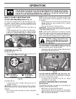
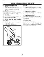
DECK WASHOUT PORT (See Fig. 32)

Your tractor’s deck is equipped with a washout port on 

its surface as part of its deck wash system. It should be 

utilized after each use. 
1.  Drive the tractor to a level, clear spot on your lawn, near 

enough to a water spigot for your garden hose to reach.

IMPORTANT

: Make certain the tractor’s discharge chute is 

directed AWAY from your house, garage, parked cars, etc. 

Remove bagger chute or mulch cover if attached.
2. Make sure the attachment clutch control is in the 

“DIS EN GAGED” position, set the parking brake, and 

stop the engine.

3.  Thread the nozzle adapter (packaged with your tractor’s 

Operator’s Manual) onto the end of your garden hose. 

4.  Pull back the lock collar of the nozzle adapter and push 

the adapter onto the deck washout port at the left end 

of the mower deck. Release the lock collar to lock the 

adapter on the nozzle. 

IMPORTANT

: Tug hose ensuring connection is secure.

5.  Turn the water on.
6.  While sitting in the operator’s position on the tractor, 

re-start the engine and place the throttle lever in the 

Fast "

" position. 

IMPORTANT

: Recheck the area making certain the area 

is clear. 
7.  Move the tractor’s attachment clutch control to the “EN-

GAGED” position. Remain in the operator’s position with 

the cutting deck engaged until the deck is cleaned. 

8. Move the tractor’s attachment clutch control to the 

“DIS EN GAGED” position. Turn the ignition key to the 

STOP position to turn the tractor’s engine off. Turn the 

water off.

9.  Pull back the lock collar of the nozzle adapter to discon-

nect the adapter from the nozzle washout port. 

10. Move the tractor to a dry area, preferably a concrete or 

paved area. Place the attachment clutch control in the 

“ENGAGED” position to remove excess water and to 

help dry before putting the tractor away. 


WARNING: A broken or missing washout 

fitting could expose you or others to 

thrown objects from contact with the blade.

• 

Replace broken or missing washout fitting 

immediately, prior to using mower again. 

• 

Plug any holes in mower with bolts and locknuts.

Fig. 32

WASHOUT 

PORT

NOZZLE ADAPTER

HOSE

00667

FUEL FILTER

CLAMP

CLAMP

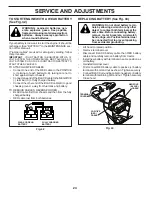
IN-LINE FUEL FILTER  (See Fig. 30)

The fuel filter should be replaced once each season.  If fuel 

filter becomes clogged, ob struct ing fuel flow to car bu re tor, 

re place ment is re quired.
• 

With engine cool, remove filter and plug fuel line sec tions.

•  Place new fuel filter in position in fuel line with arrow 

pointing towards carburetor.

•  Be sure there are no fuel line leaks and clamps are 

properly positioned.

•  Immediately wipe up any spilled gasoline.

Fig. 30

Fig. 31

• 

Keep finished surfaces and wheels free of all gasoline, 

oil, etc.

•  Protect painted surfaces with automotive type wax.
We do not recommend using a garden hose or pressure 

washer to clean your tractor unless the engine and trans-

mission are covered to keep water out. Water in engine or 

transmission will shorten the useful life of your tractor.  Use 

compressed air or a leaf blower to remove grass, leaves 

and trash from tractor and mower.

CLEANING

•  Clean engine, battery, seat, finish, etc. of all foreign 

matter.

•  Clean debris from steering plate.  Debris can restrict 

clutch/brake pedal shaft movement, causing belt slip 

and loss of drive.

CAUTION:  

Avoid all pinch points and 

movable parts (See Fig. 31)

CLUTCH/BRAKE PEDAL

STEERING 

PLATE

STEERING SYSTEM, 

DASH, FENDER AND 

MOWER NOT SHOWN

CLEAN TOP SIDE

CAUTION:

PINCH 

POINTS

MAINTENANCE

Summary of Contents for D25K48YT

Page 1: ...Operator s Manual D25K48YT 435068 02 10 10 AP Printed in the U S A...

Page 2: ...p engine and remove keys before dismounting Disengage blades when not mowing Shut off engine and wait for all parts to come to a complete stop before cleaning the machine removing the grass catcher or...

Page 3: ...h towed equipment except at the hitch point Follow the manufacturer s recommendation for weight limits for towed equipment and towing on slopes Never allow children or others in or on towed equipment...

Page 4: ...oper tools to service or repair this tractor Please read and retain this manual The instructions will enable you to assemble and maintain your tractor properly Always observe the SAFETY RULES CUSTOMER...

Page 5: ...Wheel 5 Large Retainer Springs 7 16 2 Smaller Retainer Springs 5 16 1 Locknut 3 8 16 1 Oil Drain Tube For Future Use 1 Shoulder Bolt Mower Front Wheel 1 Anti Sway Bar 1 3 4 O D Washers 1 1 1 4 O D Was...

Page 6: ...stments section in this manual Fig 1 LABEL ADJUST SEAT See Fig 2 Sit in seat Lift up adjustment lever A and slide seat until a com fortable position is reached which allows you to press clutch brake p...

Page 7: ...4 SLIDE MOWER UNDER TRACTOR See Fig 8 Bring belt forward and check belt for proper routing in all mower pulley grooves NOTE Be sure mower side suspension arms A are point ing forward before sliding mo...

Page 8: ...t F Insert other end of link E into hole in front mower bracket H and secure with washer and small retainer spring J NOTE Requires deck lifting Fig 14 FRONT LINK LOCATION E G F M E FRONT LIFT LINK ASS...

Page 9: ...manual CHECKLIST BEFORE YOU OPERATE YOUR NEW TRACTOR WE WISH TO ASSURE THAT YOU RECEIVE THE BEST PERFORMANCE AND SATISFACTION FROM THIS QUALITY PRODUCT PLEASE REVIEW THE FOLLOWING CHECKLIST All assem...

Page 10: ...ty inform ation about hazards which can result in death serious injury and or property damage DANGER indicates a hazard which if not avoided will result in death or serious injury WARNING indicates a...

Page 11: ...ctor F IGNITION SWITCH Used for starting and stopping the engine G REVERSE OPERATION SYSTEM ROS ON POSITION Allows operation of mower or other powered attachment while in reverse H LIGHT SWITCH Turns...

Page 12: ...nd full speed fast position before stopping may cause engine to backfire Turnignitionkey F to STOP positionandremovekey Always remove key when leaving tractor to prevent unauthorized use Never use the...

Page 13: ...ctorshield S in place See Fig 23 TO STOP MOWER BLADES Disengage attachment clutch control FIG 23 J K L S TO USE CRUISE CONTROL J See Fig 20 Thecruisecontrolfeaturecanbeusedforforwardtravelonly SYSTEM...

Page 14: ...ment clutch engaged will shut off the engine unless ignition key is placed in the ROS ON position WARNING Backing up with the attachment clutch en gaged while mowing is strongly discouraged Turning th...

Page 15: ...for normal operation OPERATION TO START ENGINE See Fig 16 When starting the engine for the first time or if the engine has run out of fuel it will take extra cranking time to move fuel from the tank...

Page 16: ...After one or two rounds mow in the opposite direction making left hand turns until finished See Fig 26 Fig 26 If grass is extremely tall it should be mowed twice to reduce load and possible fire haza...

Page 17: ...e warranty on this tractor does not cover items that have beensubjectedtooperatorabuseornegligence Toreceive full value from the warranty operator must maintain tractor as instructed in this manual So...

Page 18: ...witch in the ROS ON position and the attachment clutch engaged any attempt by the operator to shift into reverse should NOT shut off the engine BLADE CARE Forbestresultsmowerbladesmustbekeptsharp Repl...

Page 19: ...mely dusty dirty conditions remove the blower housing and other cooling shrouds Clean the cooling fins and external surfaces as necessary Ensure the cooling shrouds are reinstalled NOTE Operating the...

Page 20: ...the tractor to a dry area preferably a concrete or paved area Place the attachment clutch control in the ENGAGED position to remove excess water and to help dry before putting the tractor away WARNING...

Page 21: ...ee Fig 34 MOWER DRIVE BELT REMOVAL Park tractor on a level surface Engage parking brake Lower attachment lift lever to its lowest position Disengage belt tension rod K from lock bracket L CAUTION Belt...

Page 22: ...ppearance Readjust if necessary until you are satisfied with the results A Turn nut left to lower mower Turn nut right to raise mower Fig 35 Fig 36 PRECISION SIDE TO SIDE ADJUSTMENT See Fig 36 With al...

Page 23: ...tall mower See TO INSTALL MOWER section in this manual electric 02953 E A F B J G C H D Fig 39 TO CHECK BRAKE If tractor requires more than five 5 feet to stop at highest speed in highest gear on a le...

Page 24: ...rom fuel tank and battery TO REMOVE CABLES REVERSE ORDER BLACK cable first from chassis and then from the fully charged battery RED cable last from both batteries WEAK OR DEAD BATTERY FULLY CHARGED BA...

Page 25: ...e procedure ENGINE TO ADJUST THROTTLE CONTROL CABLE The throttle control has been preset at the factory and adjustment should not be necessary If adjustment is nec essary see engine manual TO ADJUST C...

Page 26: ...UELSYSTEMPARTSSUCH AS CARBURETOR FUEL FILTER FUEL HOSE OR TANK DURING STORAGE ALSO EXPERIENCE INDICATES THAT ALCOHOL BLENDED FUELS CALLED GASOHOL OR USING ETHANOLORMETHANOL CANATTRACTMOISTUREWHICH LEA...

Page 27: ...ng 7 Faulty ignition switch 7 Check replace ignition switch 8 Faulty solenoid or starter 8 Check replace solenoid or starter 9 Faulty operator presence switch es 9 Contact an authorized service center...

Page 28: ...ed 9 Reinstall blades sharp edge down 10 Improper blades used 10 Replace with blades listed in parts manual 11 Cloggedmowerdeckventholesfrombuildup of grass leaves trash around mandrels 11 Clean aroun...

Page 29: ...never across the face Do not mow slopes greater than 15 degrees Make turns gradually to prevent tipping or loss of control Exercise extreme caution when changing direction on slopes 1 Fold this page a...

Page 30: ...s used for rental or commercial purposes is limited to 90 days from the date of original purchase 5 This Warranty applies only to products which have been properly assembled adjusted operated and main...

Reviews: