background image

18

WARNING: TO AVOID SERIOUS INJURY, BEFORE PERFORMING ANY SER VICE OR AD JUST MENTS:

  Depress brake pedal fully and set parking brake.

  Place attachment clutch  in “DISENGAGED” position.

  Turn ignition key to “STOP” and remove key.

  Make sure the blades and all moving parts have completely stopped.

  Disconnect spark plug wire from spark plug and place wire where it cannot come in contact  with plug.

SERVICE AND ADJUSTMENTS

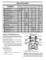
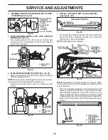
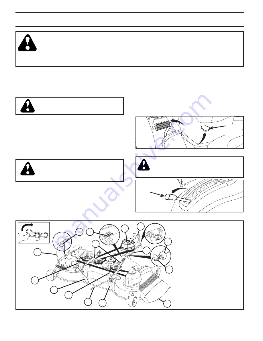
A.  MOWER SIDE SUSPENSION 

ARMS

B. RETAINER SPRING
C.  REAR LIFT LINK(S)
D.  RIGHT SIDE REAR MOWER 

BRACKET

E.  FRONT LIFT LINK ASSEMBLY
F.  FRONT SUSPENSION BRACKET
H.  FRONT MOWER BRACKET
I.  LEFT SIDE REAR MOWER 

BRACKET

K.  BELT TENSION ROD
L. LOCKING BRACKET
M.  ENGINE CLUTCH PULLEY
Q. DEFLECTOR SHIELD
S. ANTI-SWAY BAR
W.  FRONT GAUGE WHEEL

E

A

M

F

B

K

C

C

S

W

H

Q

I

D

L

Fig. 20

LIFT 

LEVER

Fig. 22

TO INSTALL MOWER (See Figs. 20 - 32)

1. SET PARKING BRAKE LEVER AND LOWER AT-

TACHMENT LIFT LEVER (See Fig. 21 and 22)

•  Depress clutch/brake pedal all the way down and hold.
•  Pull parking brake lever up and hold, re lease pres sure 

from clutch/brake pedal, then release parking brake 

lever.  Pedal should re main in brake position.  Ensure 

parking brake will hold tractor secure.

PARKING 

BRAKE 

LEVER

Fig. 21

CAUTION: Lift lever is spring loaded. Have a 

tight grip on lift lever, lower it slowly and en-

gage in lowest position.  Lift lever is located 

on left side of fender.

TO REMOVE MOWER (See Fig. 20)

•  Place attachment clutch in “DIS EN GAGED” position.

•  Lower attachment lift lever to its lowest position.

•  Disengage belt tension rod (K) from lock bracket (L).

CAUTION: Belt tension rod is spring 

loaded. Have a tight grip on rod and 

release slowly.

•  Remove mower belt from electric clutch pulley (M).
• 

Disconnect front link (E) from mower - remove retainer 

spring and washer.

• 

Go to either side of mower and disconnect mower suspen-

sion arm (A) from chassis and rear lift link (C) from rear 

mower bracket (D) - remove retainer springs and washers. 

• 

Go to other side of mower and disconnect the suspen-

sion arm and rear lift link.

CAUTION: After rear lift links are discon-

nected, the attachment lift lever will be 

spring loaded. Have a tight grip on lift le-

ver when changing position of the lever.

• 

From right side of mower, disconnect anti-sway bar (S) 

from right rear mower bracket (D) - remove retainer 

spring and washer and pull mower toward you until the 

bar falls from the hole in bracket. 

• 

Turn tractor steering wheel to the left as far as it will go.

•  Slide mower out from under right side of tractor.

Summary of Contents for D25KH48

Page 1: ...erator s Manual D25KH48 532 43 66 69 Rev 8 Gasoline containing up to 10 ethanol E10 is acceptable for use in this machine The use of any gasoline exceeding 10 ethanol E10 will void the product warrant...

Page 2: ...ook down and behind before and while backing Never direct discharged material toward anyone Avoid dischargingmaterialagainstawallorobstruction Material may ricochet back toward the operator Stop the b...

Page 3: ...OF GASOLINE To avoid personal injury or property damage use extreme care in handling gasoline Gasoline is extremely flammable and the vapors are explosive Extinguish all cigarettes cigars pipes and o...

Page 4: ...rage sections of this manual Wear proper Personal Protective Equipment PPE while operating this machine including at a minimum sturdyfootwear eyeprotection andhearingprotection Do not mow in shorts an...

Page 5: ...are in the operating position seated behind the steering wheel Key s Slope Sheet Battery Keys 1 Oil Drain Tube 2 Hex Bolts 2 Nut Keps Installed by Dealer Brush Guard Kit LABEL Fig 1 ADJUST SEAT See Fi...

Page 6: ...perly inflated for leveling Check mower and drive belts Be sure they are routed properly around pulleys and inside all belt keepers Check wiring See that all connections are still secure and wires are...

Page 7: ...ety inform ation about hazards which can result in death serious injury and or property damage DANGER indicates a hazard which if not avoided will result in death or serious injury WARNING indicates a...

Page 8: ...or F IGNITION SWITCH Used for starting and stopping the engine G REVERSE OPERATION SYSTEM ROS ON POSITION Allows operation of mower or other powered attachment while in reverse H LIGHT SWITCH Turns th...

Page 9: ...tractor com pletely as described above and set parkingbrakebeforeleavingtheopera tor s position NOTE Failure to move throttle control between half and full speed fast position before stopping may cau...

Page 10: ...r turning With forward drive pedal depressed to desired speed pull cruise control lever J up and hold while lifting your foot off the pedal then release the lever To disengage the cruise control depre...

Page 11: ...tion key clockwise to engine ON position ROS ON POSITION ENGINE ON POSITION NORMAL OPERATING 02828 TO OPERATE ON HILLS CAUTION Donotdriveupordownhills with slopes greater than 15 and do not drive acro...

Page 12: ...until the engine begins to run smoothly Continue to push the choke control in small steps allowing the engine to acceptsmallchangesinspeedandload untilthechoke control is fully in If the engine starts...

Page 13: ...ol to half 1 2 speed Disengage parking brake 8 Drive tractor forward for approximately five feet then backwards for five feet Repeat this driving procedure three times Your transmission is now purged...

Page 14: ...RECOMMENDATIONS The warranty on this tractor does not cover items that have beensubjectedtooperatorabuseornegligence Toreceive full value from the warranty operator must maintain tractor as instructe...

Page 15: ...s running with the ignition switch in the ROS ON position and the attachment clutch engaged any attempt by the operator to shift into reverse should NOT shut off the engine BLADE CARE Forbestresultsmo...

Page 16: ...60 5W 30 10W30 ENGINE LUBRICATION Only use high quality detergent oil rated with API service classification SG SL Select the oil s SAE viscosity grade according to your expected operating temperature...

Page 17: ...ashout fitting immediately prior to using mower again Pluganyholesinmowerwithboltsandlocknuts Fig 19 DECK WASHOUT PORT See Fig 19 Your tractor s deck is equipped with a washout port on its surface as...

Page 18: ...re parking brake will hold tractor secure PARKING BRAKE LEVER Fig 21 CAUTION Lift lever is spring loaded Have a tight grip on lift lever lower it slowly and en gage in lowest position Lift lever is lo...

Page 19: ...l go and position mower on right side of tractor with deflector shield Q to the right 2 ASSEMBLEFRONTGAUGEWHEEL W TOFRONT OF MOWER See Fig 23 NOTE Depending on model bracket T may be differ ent than s...

Page 20: ...EAR LIFT LINKS C See Fig 30 Insert rod end of rear lift link C into hole U in tractor lift shaft suspension arm and pivot link down to mower Lift rear corner of mower and position slot in link as semb...

Page 21: ...ly checking the appearance Readjust if neces sary until you are satisfied with the results A TURN NUT LEFT TO LOWER MOWER TURN NUT RIGHT TO RAISE MOWER Fig 33 Fig 34 PRECISION SIDE TO SIDE ADJUSTMENT...

Page 22: ...F Be sure belt is inside the belt keeper 4 Install belt on centerspan idler E 5 Installbeltthroughstationaryidler C andclutchingidler D 6 Reinstall anti rotation link B on right side of tractor Tight...

Page 23: ...R VEHICLES TO ATTACH JUMPER CABLES Connect one end of the RED cable to the POSITIVE terminal of each battery A B taking care not to short against tractor chassis ConnectoneendoftheBLACKcabletotheNEGAT...

Page 24: ...bulb holder securely back into the hole in the backside of the grill Close hood INTERLOCKS AND RELAYS Loose or damaged wiring may cause your tractor to run poorly stop running or prevent it from star...

Page 25: ...Plastic cannot breathe which allows condensation to form and will cause your tractor to rust IMPORTANT NEVER COVER TRACTOR WHILE ENGINE AND EXHAUST AREAS ARE STILL WARM Immediately prepare your tracto...

Page 26: ...eck replace ignition switch 8 Faulty solenoid or starter 8 Check replace solenoid or starter 9 Faulty operator presence switch es 9 Contact an authorized service center department Engine clicks but wi...

Page 27: ...mower drive belt 9 Blades improperly installed 9 Reinstall blades sharp edge down 10 Improper blades used 10 Replace with blades listed in parts manual 11 Cloggedmowerdeckventholesfrombuildup of gras...

Page 28: ...never across the face Do not mow slopes greater than 15 degrees Make turns gradually to prevent tipping or loss of control Exercise extreme caution when changing direction on slopes 1 Fold this page a...

Page 29: ...29 SERVICE NOTES...

Page 30: ...30 SERVICE NOTES...

Page 31: ...31 SERVICE NOTES...

Page 32: ...11 26 14 AP Printed in the U S A...

Reviews: