background image


SPECIFICATIONS


The monocoque design chassis of the Model ZTR 1001 incorporates CMC laser 
and CNC brake processes to form the twin 12 gauge side frames and 7 gauge 
transmission and engine base plate.


The front body cover is made of rotational molded polyethylene. Front body 
contains access panel for battery service.


Cut height approximately 1" to 4" via 7 position lift handle. 
Each deck is stamped steel construction:


36"-11 gauge 2 blades  
36" cut width


Electric clutch.


Each rear wheel is independently driven by chain and sprockets th rough a  friction 
mechanical drive.


15HP Kohler Command, 4-Cycle, Single Cylinder, Overhead Valve, Air-Cooled, 
Pressure Lubricated, With Oil Filter, Vertical Shaft, Aluminum Head and Block with 
Cast Iron Cylinder Liner.


Electric by key switch operation with safety interlocks on parking brake and blade 
drive.


Front 

9 X 350 X 4 ribbed tread.                 


Rear 

1 6 X 6 . 5 0  X 8 Multi Trac Tread.                                                   .


Fuel: 

2.7 gallons total


Engine: 

2 quarts oil.


Width 

Overall width with deflector retracted:


36" deck: 39"     42" deck: 46 1/2"   50" deck: 52 1/2"


Length       77" overall.


Weight       36" deck: 494 Ibs.       42" deck: 510 Ibs.        50" deck: 532 Ibs.


Additional information provided in service instructions underthe individual 
component.


SPECIFICATIONS SUBJECT TO CHANGE WITHOUT NOTICE


Model ZTR 1001


CHASSIS:


BODY:


MOWER DECKS:


42"-13 gauge 3 
blades  
42" cut width


50"-10 gauge 
3 blades  
50" cut width


BLADE DRIVE: 

TRANSMISSION:


ENGINE:


STARTING SYSTEM:


TIRES:


CAPACITIES:


DIMENSIONS:


NOTE:


Page8


Summary of Contents for ZTR 1001

Page 1: ...OPERATORS MANUAL...

Page 2: ...ead the operator s manual carefully and become completely familiar with the controls The information in this operator s manual applies to your Di xon ZTR Model ZTR 1001 Mower Your Dixon dealer will gl...

Page 3: ...CY Page 7 SPECIFICATIONS Page 8 CONTROLS Pages 9 12 OPERATION INSTRUCTIONS Pages 13 18 CARE AND MAINTENANCE Pages 19 26 STANDARD SERVICE PARTS LIST Page 27 TROUBLESHOOTING Pages 28 30 DIAGRAMS Pages 3...

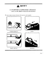
Page 4: ...LA WNMOWERS IF IMPROPERLY OPERATED CAN CAUSE SERIOUS INJURY OR DEATH The most common causes of injury to the operator or bystander SAFETY UPHILL THROWN OBJECTS BLADE CONTACT DOWNHILL Page 1...

Page 5: ...imminently hazardous situation which if not avoided will result in death or serious injury Warning indicates a potentially hazardous situation which if not avoided could result in death or serious inj...

Page 6: ...and while backing Be aware of the mower discharge direction and do not point it at anyone Do not operate the mower without either the entire grass catcher or the deflector in place Slow down before t...

Page 7: ...hments These can change the stability of the mower Keep all movement on the slopes slow and gradual Do not make sudden changes in speed or direction Avoid starting or stopping on a slope If tires lose...

Page 8: ...t of the mowing area and under the watchful care of another responsible adult Be alert and turn mower off if a child enters the area Before and during backing look behind and DOWN for small children N...

Page 9: ...mower free of grass leaves or other debris buildup Clean up oil or fuel spillage Allow mower to cool before storing Stop and inspect the equipment if you strike an object Repair if necessary before r...

Page 10: ...it or incidents of misuse negligence accidents or alteration The use of parts or components other than those supplied by Dixon Industries Inc VOIDS ALL WARRANTY 6 The following items arenot covered by...

Page 11: ...verhead Valve Air Cooled Pressure Lubricated With Oil Filter Vertical Shaft Aluminum Head and Block with Cast Iron Cylinder Liner Electric by key switch operation with safety interlocks on parking bra...

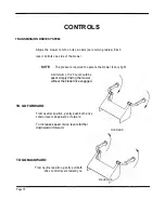
Page 12: ...in stopping the mower while it is in motion NOTE Engine cannot be started unless the brake is applied Do not leave engine running for extended periods of time without the parking brake engaged TO SET...

Page 13: ...e mower is very light A minimum of 1 2 hour should be spent simply driving the mower without the blade drive engaged TO GO FORWARD From neutral position gently push both drive control levers downward...

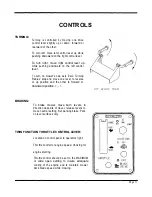
Page 14: ...n setting to insure adequate cooling of the engine and to maintain mower deck blade speed while mowing TURNING Turning is controlled by moving one drive control lever slightly up or down forward or re...

Page 15: ...ive switch up and push forward To disengage blades pull switch backward Switch is clearly marked ON and OFF MOWER DECK CUT HEIGHT LIFT LEVER Located to the right of operator Controls the cutting heigh...

Page 16: ...ls and their functions During initial operation set throttle at slow speed Sound judgement by the owner will prevent accidents BEFORE OPERATING MOWER 1 Readenginemanufacturer soperatingandmaintenancei...

Page 17: ...ver or attempt to start when key switch is moved to the start position b In a SAFE AREA away from bystanders start the engine place throttle setting at maximum or full Engage blade drive clutch switch...

Page 18: ...ease ignition key Key will return to run position 4 Move throttle from choke to desired speed position NOTE While mowing blade s engaged throttle control should be set to the MAXIMUM or wide open sett...

Page 19: ...y on first cuttings or if the lawn is heavily fertilized 4 Do Not Attempt To Cut Grass When It Is Wet Mulching performance will be very poor under wet grass conditions 5 Maintain Sharp Blade s Through...

Page 20: ...5 Use only the correct blade s Some grass catching attachments require a high lift blade See your dealer for advice on the type of blade s needed for your mower 6 Maintain Sharp Blade s Throughout The...

Page 21: ...with each pass Some applications may require a second cutting 4 Keep The Underside Of The Mower Deck Clean Frequent removal of dried grass and dirt will allow the clippings to discharge correctly 5 M...

Page 22: ...40 hours of use 1 Drive chain 2 Drive system belts and controls 3 Mower deck belts 4 Tire pressures 5 Tightness of all nuts and bolts 6 Battery fluid level 7 Engine oil Before performing any maintenan...

Page 23: ...ade position prior to removal 1 Safely raise front of mower 2 Hold or block blade from turning Wear heavy thick gloves when holding onto cutter blade avoid the sharp edge of the blade NOTE Be sure bla...

Page 24: ...movement of the belt idler will be observed both during engagement of the electric blade clutch and actual operation of the mower deck NOTE Engagement of the electric blade clutch switch may produce...

Page 25: ...mension shown in the illustration below CHASSIS Number of grease zerks used 4 LOCATIONS 1 each front wheel caster and each front wheel hub SERVICE INTERVALS Every 50 hours of operation RECOMMENDED GRE...

Page 26: ...d remove handle through hole in lower body 6 Remove pin and washer from one end of deck support shaft Note location of remaining shim washers used between chassis and mower deck pan arms Slide shaft f...

Page 27: ...he oil 3 Pus i the valve body in and twist to clear the detent notch 4 Pulling MC Q valve body outward will start the flow of oil Refer to engine manufacturers recommendations for frequency of oil cha...

Page 28: ...es must be inflated to proper specifications 2 Rear drive chain tension 3 Tightness of all controls and linkages pertaining to the drive levers 4 Lubrication of both primary and final drive chains The...

Page 29: ...e at rear of engine it will begin with DM Refer to Warranty Registration Form P N 8871 See your Dixon dealer for replacement parts warranty or service PLEASE HELP PROTECT THE ENVIRONMENT BY AVOIDING A...

Page 30: ...Please refer to Kohler Engine Operators Manual for correct service intervals for engine oil changes and air filter maintenance Protect your engine investment use only original equipment filters The co...

Page 31: ...le to provide assistance to you Poor cut quality Engine RPM too low Increase engine RPM to maximum Poor cut quality Ground speed Reduce mowing speed Poor cut quality Grass buildup under mower deck Cle...

Page 32: ...Mower pulls to one side or the other Drive adjustment Consult your dealer for repair DRIVE SYSTEM SITUATION REMEDY CAUSES Poor driving performance Operation of mower Review operators section of owners...

Page 33: ...your dealer Engine being operated Increase engine RPM at too low an RPM Contact your dealer for information NOTE Electrical system failures are generally simple in nature always check the obvious fir...

Page 34: ...Page 31...

Page 35: ...Page 32...

Page 36: ...Page 33...

Page 37: ...Page 34...

Page 38: ...Page 35...

Page 39: ...Page 36...

Page 40: ...c A International Inc Company P O Box 1569 Coffeyville KS 67337 0945 316 251 2000 OWNER INFORMATION DATE PURCHASED MOWER MODEL NUMBER PURCHASED FROM Name Address MOWER SERIAL NUMBER PM DATE OIL CHANGE...

Page 41: ...of California to cause cancer birth defects or other reproductive harm Dixon and ZTR are registered trademarks of Dixon Industries Inc Dixon Industries Inc A International Inc Company P O Box 1569 Cof...

Reviews: