9/89 (Revised)
Page 1
TECHNICAL DATA BROCHURE
(MODEL ZTR 304)
IMPORTANT - READ OPERATOR'S MANUAL BEFORE OPERATING OR MAKING ADJUSTMENTS
BODY REMOVAL
1. The 304 has a ( 2 ) piece fabricated s t e e l body. The upper body can be folded
forward to expose t h e t r a n s a x l e . In s o m e cases, it may be necessar y to remove
the upper body to s e r v i c e t h e transaxle.
\
2.
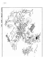
To remove upper body, fold f o r w a r d and r e m o v e b o l t (P/N 3 0 0 6 ) from cable (P/N
3780). Shut upper body and remove the t w o c o t t e r pines (P/N 3058) fro m t h e
front of upper body s u p p o r t . C a r e f u l l y l i f t upper body from frame.
3. Reverse above procedure to reinstall.
SEAT ADJUSTMENT
1. Raise upper body.
2.
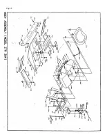
Loosen four s e a t bolts (P/N 3093) and slide s e a t forward or backward to
desired position.
3. Retighten bolts.
MOWER BLADE OPERATION
To engage the mower blades, t u r n lever on floor slowly to the "ON" position. To
disengage mower blades, t u r n l e v e r slowly to the "OFF" position.
REMOVING MOWER DECK
*
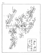
1. Loosen the belt keeper (P/N 7 0 2 6 & 7 0 2 7 ) , located under the engine, by l o o s i n g
t w o r e a r engine mounting b o l t s , allowing the deck d r i v e belt to come f r e e of the
r e a r pulley.
2. Disconnect the w i r i n g loom at t h e deck s a f e t y switch (P/N 4242).
3. Remove* the two clevis pins (P/N 3 0 7 2 ) f r o m the two r e a r L- r o d s (P/N 1355) and
slide f r o m slots.
4. Remove clevis pins (P/N 3 0 7 2 ) L-rod a t t a c h e d to l i f t handle and slide from slot.
5. Remove clevis pin (P/N 3 0 7 2 ) f r o m f r o n t deck hanger' s h a f t (P/N 1332), located at
f r o m of mower deck on slide p l a t e s w e l d e d at b a t t e r y box and remove.
6. Lift front of mower c h a s s i s and roll f r e e of t h e deck.
7. To install, reverse the above procedure.
IDJUSTMENT OF MOWER DECK DRIVE BELT
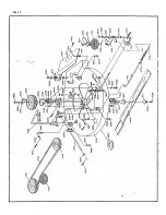
1. The m o w e r deck d r i v e belt is t e n s i o n e d by a s p r i n g loaded engagement idler
quadrant.
2. This system is designed to maintain the proper belt tension at all times.
3. Belt tension can be adjusted by moving the engaging rod (P/N 7013) into the
outside hole of engagement handle (P/N 7020).
4. A f t e r belt tension is adjusted, check to assure that the mower blade will not
t u r n freely when the engaging rod is in the "OFF" position.
5. If the mower blade .urns freely, a d j u s t the blade by loosening*nut' (P/N 3205) at
end of the brake linkage (P/N 7015).
6. A f t e r adjustment is achieved, perform the safety checks listed below.
Summary of Contents for ZTR 304
Page 3: ...Page 3...
Page 4: ...Page 4...
Page 5: ...Page 5...
Page 6: ...Page 6...
Page 7: ...Page 7...


