background image

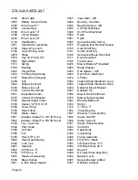
ZTR 5421 PARTS LIST


4584


Start Cable


5643


Input Gear - GB


4585


Battery Ground Cable


5644


Bearing - Gearbox


4587


Wire Cover 61 "


5645


Bearing Spacer - GB


4589


Covered Key


5648


CW Fan-Machined


4594


Wire Cover 14"


5649


CCW Fan-Machined


4598


Circuit Breaker


5650


Hydro


4645


Wire Cover 30"


5651


Hydro


4733


Seat Bottom


6065


Serpentine Idler Spring


4761


Seat Switch Assembly


6075


Engaging Idler Bracket Spacer


4783


Upper Wire Loom


6100


Outer Shaft Key


4784


Lower Wiring Loom


6101


Center shaft Key


4979


Hinge


6109


Serpentine Blade Drive Belt


5070


Key 3/16" SqX 7/8"


6111


Deck Drive Belt


5085


Brake Band


6168


Trash Guard


5170


Spring


6236


Mower Blade 42" Standard


5189


Bushing


6260


Blade Washer


5242


Plug w/Hole


6263


Hub Spacer - .459


5249


5/8" Bearing w/Snap


6264


Deck Hub - Machined


5257


Brake Drum (Keyed)


6272


V-Pulley


5283


Link


6282


Tapped Shaft Weldment Long


5522


Brake Link Right


6283


Tapped Shaft Weldment Short


5525


Brake Link Left


6293


Deflector Mount Bracket


5530


Control Pivot Shaft


6297


Deflector Pin


5531


Adjustable Collar


6366


Mower Deck Weldment


5537


Control Arm Bracket


6370


Mower Deck Assembly


5540


Neutral Adjust Collar


6392


Blow-By Baffle 42"


5554


Spacer 1/2" OD X 1/4"


6744


Spring


5558


Hose Fitting                          


7015


"L" Rod - 7"


5559


Hose Fitting      


7594


Thrust Bearing


5560


Elbow - Male


7647


Wheel & Tire Assembly


5561


Adapter - Male (For 3/8" ID Hose)


7648


Caster Axle RH


5562


Adapter - Male (For 5/8" ID Hose)


7649


Caster Axle LH


5563


Tee - Cast Iron


8167


Caster Wheel Bearing


5564


Filter Head


8244


Clutch Kit


5565


Oil Filter


8384


Upper Body


5585


Tab


8386


Lower Body


5595


Hose 5/8" X 14"


8389


Frame Assembly


5602


Hose Guard Spring


8390


Front Rim - Black


5624


Tank Cap


8393


3/8" Black Hose 3.75


5625


Gearbox


8394


3/8" Black Hose 28.5


5632


3/8" Hose - 5"


8395


Wire Kit


5633


5/8" Hose - 2"


8429


Oil Valve/Hose Assembly


5635


Reservoir Assembly


8452


Battery Cover


5636


Brass Ferrule


8455


Serpentine Idler w/Stud


5641


G-Box Mount Spacer


8457


Deflector w/Decal


Page 34


Summary of Contents for ZTR 5421

Page 1: ......

Page 2: ...perator s manual carefully and become completely familiar with the controls The information in this operator s manual applies to all Dixon ZTR Model 5421 Mowers Your Dixon dealer will gladly provide a check out ride and answer any questions See your dealer for warranty service parts and repairs DIXON INDUSTRIES INC A BLOUNT COMPANY AIRPORT INDUSTRIAL PARK PO BOX 1569 COFFEYVILLE KS 67337 O945 316 ...

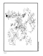
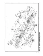
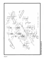
Page 3: ...ANTY POLICY Page 4 3 SPECIFICATIONS Page 5 4 SET UP AND SERVICE Pages 6 11 5 OPERATION INSTRUCTIONS Pages 12 3 6 CARE AND MAINTENANCE Pages14 21 7 TROUBLESHOOTING Pages 22 24 8 PARTS ILLUSTRATIONS Pages 25 31 9 PARTS LIST Pages 32 35 ...

Page 4: ... slopes when the grass is dry and watch for bumps holes and other obstacles Test the slope with the blades off A good rule of thumb is Don t mow on a slope you can t back up Stay clear of drop offs especially if they are on the down side of a slope 4 THROWN OBJECTS The fast spinning mower deck blade can strike stones or other objects which can be hurled into the path of a bystander To prevent this...

Page 5: ...ttended Your Dixon mower is equipped with a weight sensitive switch that kills the engine when operator leaves the seat while blades are engaged Note This important safety feature must be tested prior to each mowing This may be done by starting engine engaging blades and then rising slightly from seat If engine does not stop see your dealer for necessary repair 10 Before adjusting or servicing you...

Page 6: ...nd screws tight to be sure the mower is in safe working condition 20 To reduce fire hazard keep the engine free of grass leaves or excessive grease 21 The mower should be stopped and inspected for damage after striking a foreign object or if it starts vibrating and any damage should be repaired before restarting and operating the mower 22 When mowing proceed as follows A Mow only in daylight or in...

Page 7: ...anty Limited to 90 days from date of purchase 4 Accessories Warranty Grass Catchers Snow Blades Tine Rakes Covers etc Limited to 90 days from date of purchase 5 Warranty does not apply to damage in transit or incidents of misuse negligence accidents or alteration The use of parts or components other than those supplied by Dixon Industries Inc VOIDS ALL WARRANTY 6 The following items are not covere...

Page 8: ...es 70 hydrostatic transmissions are serviced with any high quality 10W 30 motor oil The oil is filtered by a 10 micron oil filter Recommended service interval for filter is after the first 250 hours of operation then after every 400 hours of operation If the system becomes contaminated by dirt or other foreign debris both oil and filter must be replaced immediately ENGINE 16 HP Kohler Magnum Verti...

Page 9: ...SET UP AND SERVICE 1 Seat Assembly Instructions 2 Upper Control Lever Installation 3 Mower Deck Installation 4 Deck Leveling 5 Final Preparation Page 6 ...

Page 10: ...Tighten all seat hardware at this time 5 Place seat assembly on body and connect seat safety switch 6 Place 1 seat spacer 1849 on each stud protruding through seat bottom and insert studs through slots in body Firmly hold seat assembly against body with one hand while body is raised to fully open position Continue to hold seat against body to prevent damage to seat safety switch wiring 7 Install 1...

Page 11: ...hen second flat washer 3 Push control lever into the neutral slot and install 2 cup washers 1 flat washer and jam nut See illustration 4 Tighten jam nut Proper tightness or tension on jam nut is achieved when swing out movement of upper control levers requires some pressure Levers should not fall to the side or be sloppy in movement 5 Repeat above procedure on left side Page 8 ...

Page 12: ...nger rods on lift frame Slide lift plate on hanger rods small holes in lift plate will face rear of mower and start nylok nuts on each hanger rod until approximately 1 2 inch of threads are exposed 3 Position mower deck under chassis 4 Raise front of mower deck and slide front support rod through lift frame and tabs on mower deck Install hair pin clips on front and rear of support rods 5 Move lift...

Page 13: ...Move to the opposite side check that measurement is the same If adjustment is required turn the nut on the bottom of the front threaded adjuster up or down until both side to side measurements are equal Retain measurement D Rotate or turn both outer blades to align with the deck in front to rear manner Move to the left rear threaded adjuster left rear is designated from operator position on the mo...

Page 14: ...er battery polarity when re connecting leads on chassis Always connect positive lead first ENGINE SERVICE Final preparation of engine should be completed using engine service manual provided with mower INITIAL START AND HYDROSTAT TRANSMISSION CHECK 1 Final hydrostat checks have been performed at the factory however it is necessary to check that the pressure relief bypass on each hydrostatic transm...

Page 15: ...VE SYSTEM Allows the mower to turn on its own axis zero radius Each lever controls one side of the mower The pressure required to operate the mower is very light and a minimum of 112 hour should be spent simply driving the mower in a non mowing application to gain the confidence necessary to mow like a pro LEVER MOVEMENTS No shifting or clutching required TO GO FORWARD Release parking brake From n...

Page 16: ...ould be set to the maximum or wide open setting to insure adequate cooling of the engine and to maintain mower deck blade speed while mowing MOWER DECK CUT HEIGHT LIFT LEVER Controls the cutting height of the mower deck Seven positions of adjustment in which the very top or highest notch is used for transporting the mower in a non mowing situation Located in front of operator on the right side of ...

Page 17: ...nit if failure should occur MAINTENANCE SCHEDULE To insure a long and trouble free service life on all the components used on the Model 5421 a regular and thorough maintenance schedule should be followed As with any type of precision made equipment a certain amount of initial bedding in or seating of the components will take place The following items should be checked after the first 10 hours of o...

Page 18: ...cate the three holes in the brakeplate one near each adjustment nut figure 2 5 Insert a 012 inch feeler gauge into one of the three windows Be careful to position the feeler gauge between the rotor and armature faces figure 3 6 Tighten the adjusting nut adjacent to the window with the feeler gauge inserted until the gauge fits snugly between the rotor and armature The gap should not be so tight th...

Page 19: ...ide deck from under chassis 3 Reverse procedure to re install deck assembly CUTTER BLADE REMOVAL 1 Carefully place deck assembly in a manner which will allow access to the blade bolts Hold blade from turning while bolt is removed from the center of each hub assembly Caution wear heavy thick gloves when holding onto cutter blade avoid the sharp edge of the blade 2 When reassembling blades to hub as...

Page 20: ...s not release drum loosen nut until achieving desired results Repeat procedure if necessary See Figure 3 4 Neutral Adjustment Swing upper control levers out into the neutral slots Raise upper body to the fully open position Start engine and disengage parking brake Caution should be used when releasing parking brake as mower may tend to creep or move prior to adjustment If adjustment is required lo...

Page 21: ...Page 18 ...

Page 22: ...FORWARD LEVER STOP ADJUSTMENT Page 19 ...

Page 23: ...s is not recommended as damage to seals and bearings could occur Using a hand pressure grease gun lubricate each front wheel to allow even distribution of grease within the wheel rotate or spin each front wheel after 3 pumps of the grease gun Repeat process until the appearance of grease is noted completely around each caster axle ENGINE OIL CHANGES OIL RECOMMENDATIONS SERVICE INTERVALS Refer to s...

Page 24: ...stiff brush can be used to loosen excess grass and dirt build up Avoid directing water pressure onto the mower deck hub assemblies electrical wiring and engine components such as air filter openings To remove excess water which accumulated during washing of the mower either blow off with compressed air if available or start the engine allowing a long enough operation time to dry thoroughly It is a...

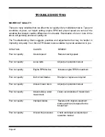
Page 25: ...ler is also available to provide assistance to you SITUATION CAUSES REMEDY Poor cut quality Ground speed Reduce mowing speed Poor cut quality Loose belts Adjust per operators manual Poor cut quality Engine RPM too low Increase engine RPM to maximum Poor cut quality Dull or bent blades Sharpen or replace as required Poor cut quality Unlevel mower deck Adjust per operators manual Poor cut quality Gr...

Page 26: ...he other T Box belts slipping Adjust per operators manual Consult your dealer for repair Loss of power on both wheels after being operated for a length of time Belt from engine to T Box is slipping Adjust per operators manual Consult your dealer for repair Poor driving performance Operation of mower Review operators section of owners manual Oil leaks Loose or missing hose clamps Tighten or replace...

Page 27: ...g correctly Have electrical system checked by your dealer Battery discharge Engine being operated at too low an RPM Increase engine RPM Contact your dealer for information Electric clutch will not engage mower deck blades Low battery condition Poor connections on clutch switch Broken wiring Repair or replace as required Consult your dealer for repair NOTE Electrical system failures are generally s...

Page 28: ...Page 25 ...

Page 29: ...Page 26 ...

Page 30: ...Page 25 ...

Page 31: ...Page 26 ...

Page 32: ...Page 27 ...

Page 33: ...Page 28 ...

Page 34: ...Page 29 ...

Page 35: ...Page 30 ...

Page 36: ...Page 31 ...

Page 37: ...HHBoltGR5 3002 5 16 18X21 2 HHBoltGR8 3231 9 1 6 Std Flat Washer 3005 5 16 18UNCHexNut 3235 10 24 X 5 8 Phillips Pan Hd Screw 3006 5 16 18X1 1 4 HH Bolt GR5 3237 Eye Bolt 5 1 6 X 6 00 3007 1 4 20 UNC Hex Nut 3247 6 20 X 1 2 Phillips Pan Hd Screw 3008 1 4 ID X 3 4 OD Flat Washer 3249 5 8 Int Tooth Lock Washer 3009 5 1 6 18 UNC X 1 3 4 HH Bolt GR5 3256 Snap Ring 3012 3 8 16UNCHexNut 3257 7 16 Int To...

Page 38: ...Right 6283 Tapped Shaft Weldment Short 5525 Brake Link Left 6293 Deflector Mount Bracket 5530 Control Pivot Shaft 6297 Deflector Pin 5531 Adjustable Collar 6366 Mower Deck Weldment 5537 Control Arm Bracket 6370 Mower Deck Assembly 5540 Neutral Adjust Collar 6392 Blow By Baffle 42 5554 Spacer 1 2 OD X 1 4 6744 Spring 5558 Hose Fitting 7015 L Rod 7 5559 Hose Fitting 7594 Thrust Bearing 5560 Elbow Ma...

Page 39: ... Control Lever w Grip Right 9164 Brake Plate 9165 Brake Plate 9171 Spacer 1 75 9172 Spacer 1 50 9174 Brake Rod 9191 Connecting Link 9196 Plate 9212 Spring Belt Tensioner 9268 Spacer 1 25 OD X 1 1 4 9280 Engine Plate 9312 Bumper Weldment 9325 Seat Frame Weldment 9329 Tie Bar Weldment 9330 Tie Bar Weldment 9332 Spring Anchor 9334 Pulley Mount Plate 9335 Pivot Shaft 9336 Pulley Shaft 9339 Rear Wheel ...

Page 40: ...Page 36 NOTES ...

Page 41: ...NOTES Page 37 ...

Page 42: ...Page 38 NOTES ...

Page 43: ...DIXON INDUSTRIES INC A BLOUNT COMPANY AIRPORT INDUSTRIAL PARK PO BOX 1569 COFFEYVILLE KS 67337 O945 316 251 2OOO FAX 316 251 4117 ...

Reviews: