background image

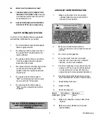
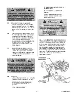
8. STEERING CONTROL ADJUSTMENTS A. 

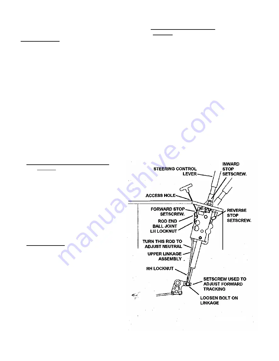
To Adjust Neutral:


a. Remove the fender skirts from each


side of the machine.


b. Block up the unit so that the Drive


Wheels are off the ground.


c. Start the engine and run at a fast idle


with the Steering control levers in the


"out" position.


d. Loosen the locknuts tightened against


the rod end ball joints in the Upper


Linkage Assembly. (Note: One of these


is a left hand nut and will have to be


turned backwards.)


e. Adjust the Neutral Position by turning


the rod in the upper linkage until the


wheel stops turning.


f. Retighten the nuts on the Upper


Linkage Assembly and check to see that


the drive wheel is still not turning.


g. Repeat steps 1-6 for the other side.


h. Shut off engine before removing the


blocks.


B. To Adjust "IN" Position of the Steering 

Controls:


a. Remove the 2 Front Bolts,


Lockwashers, and Washers which hold


the Fender Cap.


b. Pull the boot from the hole in the


fender cap, exposing the cast iron lever.


c. Using a 5/32° Alien Wrench, turn the


setscrew to adjust the stop.


d. Replace the Boot into the hole in the


Fender Cap.


c. Replace the 2 Front Bolts,


Lockwashers, and Washers.


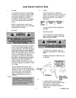
C. To Align Handles:


Sit on the seat and push the control 

levers full forward and full backward. If 

the ends do not match the handles 

maybe adjusted as follows: 

a. Locate Setscrew stops in the Steering 

Control Lever Base which stop the lever 

in each direction. (Note: The one at the 

rear is the stop for FWD and the one in 

the front is the stop for REV.) 

b.-Adjust setscrew stops so that handles 

line-up together when shifted full forward 

and full reverse. 

*'


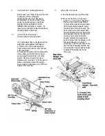
D. Adjusting for Straight Forward 

Tracking:


In a large open area, actuate the control 

handles into the full forward position. If the 

mower veers in either direction Left for 

Right some adjustment is necessary. a. If 

the mower veers to the right, then the 

right hydrostat needs to be sped up. If the 

mower veers to the left, then the left 

hydrostat need to be sped up. b. Stop the 

machine and shut off the engine.


c. Slightly loosen the bolt at the lower end 

of the upper linkage assembly on the side 

that is slower. Using a 1/8" alien wrench 

turn the setscrew 1/4 turn in. It may take 

several test drives to get the mower to 

track straight forward. d. Once the 

tracking is to the operators liking, 

completely tighten the bolt on the control 

linkage assembly that was loosened 

earlier.


e'. Recheck to make sure neutral adjust 

has not been effected, see procedure A.


9


P-11408 

(2/99) 

Summary of Contents for ZTR 700 Series

Page 1: ......

Page 2: ...tion 1 Safety Interlock Systems 3 III START UP AND OPERATION Checklist Before Operation 3 Control Locations 4 Operation 4 Mowing Recommendations 6 VI MAINTENANCE Maintenance Schedule 6 Maintenance Ins...

Page 3: ...ty does not apply to damage in transit or incidents of misuse negligence accidents or alteration The use of parts or components other than those supplied by Dixon Industries Inc VOIDS ALL WARRANTY 6 T...

Page 4: ......

Page 5: ...be trained in its proper use and warned of its dangers Before operating adjusting or servicing the Zero Turning Radius Mower they should read and understand this entire manual and the engine owner s m...

Page 6: ...cool before storing in any enclosure The engine exhaust and gasoline fumes are dangerous 14 NEVER REMOVE THE FUEL CAP or add gasoline to a running or hot engine that has not been allowed to cool for 2...

Page 7: ...Levers are moved to the IN position 6 The engine will stop if the brake is SET and the mower blade clutch is engaged CHECKLIST BEFORE OPERATION 1 Make sure fuel tank is full Use regular unleaded gaso...

Page 8: ...ed cranking will damage starter motor and shorten the battery life 7 ADJUST ENGINE THROTTLE AND CHOKE for desired engine smoothness and speed NOTE When mowing always run engine at full throttle 8 RELE...

Page 9: ...top Pin 13 ENGAGE MOWER BLADE CLUTCH Set the Blade Clutch Switch to the ON position The engine will not start if the blade clutch is engaged If the operator is not in the seat the engine will stop if...

Page 10: ...ase oil level before each use Clean grass from Hydrostat fans and cooling fans before each use Check air intake screen after each use Clean grass under deck after each use Check tire pressure every 10...

Page 11: ...ays reconnect the ground wire last Keep the battery clean Remove the corrosion around the battery terminals by applying a solution of one part baking soda to four parts water Coat all exposed terminal...

Page 12: ...moval Check the oil level on the dipstick The proper oil level should register between the marked hole on the dipstick and the end of the dipstick Replenish as needed with 20W 50 Motor Oil DO NOT OVER...

Page 13: ...To Align Handles Sit on the seat and push the control levers full forward and full backward If the ends do not match the handles maybe adjusted as follows a Locate Setscrew stops in the Steering Cont...

Page 14: ...front of the mower Remove old belt if required Replace with new belt C With the belt in place on all pullies reinsert the spring heavy washer lockwasher and 3 8 bolt Tighten 3 8 bolt fully 11 LEVELING...

Page 15: ...hoist to the deck lift bolt Lift the nose of the deck until the deck is standing vertical and the deck latch engages IMPORTANT NOTE MAKE SURE THAT THE DECK IS LIFTED FAR ENOUGH FOR THE DECK LATCH TO...

Page 16: ...12 P 11408 2 99...

Page 17: ...re loose or grounded check spark plug wires Spark plug s faulty or improperly gapped check spark plug condition and reset gap Electronic ignition defective consult dealer Dirty or maladjusted carburet...

Page 18: ...MOWER WONT MOVE FORWARD Drive belt broken or slipping replace drive belt Shift linkage cable disconnected reconnect Transmission shift arm disconnected reconnect Transmission oil low add oil Transmis...

Page 19: ...15 P 11408 2 99...

Page 20: ...NOTES...

Page 21: ...he state of California to cause cancer birth defects or other reproductive harm Dixon and ZTR are registered trademarks of Dixon Industries Inc Dixon Industries inc A BLOUNT International Inc company...

Reviews: