background image

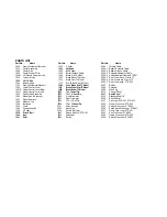
PARTS LIST


Part No. 

Name 

1000 

Frame Weldment (Electric)


1015 

Caster Assembly


1020 

Caster Axle


1022 

Caster Wheel & Tire


1029L  Lift Lever & Quadrant Left


1039 

Lower Lift Link


1040 

Lift Tie Rod 

1043 

Battery Strap


1100 

Frame Weldment (Manual)


1500 

Lower Control Lever


1501R  Upper Control Lever Right


1501L  Upper Control Lever Left


1502 

Control Rod Assembly


1504 

Wheel Hub & Sprocket


1507 

Wheel Bearings


1509 

Wheel& Tire


1528 

Bellcrank


1535 

Chain


1536 

Connecting Link


1538 

V-Pulley


1539 

Drive V-Belt 

1540 

Key 

1541 

Shim 

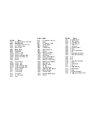
Part No.         Name 

1542 

V-Pulley


1543 

Lift Knob 

1552 

Belt Keeper


1560 

Battery Splash Guard


1564 

Brake Arm 75 Model


1567 

Brake Mount 75 Model


1574 

Brake Pivot 75 Model


1579 

Short Brake Rod 75 Model


1580 

Long Brake Rod 75 Model 

1581 

Brake Pedal Arm 75 Model 

1584 

Brake Pedal 75 Model 

3025 

1

/4 x 1 Spiral Pin 

3026 

1

/4 x 1 1/

2

 Spiral Pin 

3029 

Front Grommet


3030 

Rear Grommet


3054 

3/16 x 1 Roll Pin


3070 

1

/4 x 1 

1

/4 Spiral Pin 

3501 

Nylon Bushing


3502 

Hand Grip


3504 

Double Ball Joint


4002 

Deluxe Seat 36", ZTR-421


4003 

Headlight


4004 

Switch


Part No. 

Name 

4005 

Throttle Cable


4006-1  Battery Solenoid Cable


4006-2  Battery Ground Cable


4006-3  Solenoid-Alternator Cable


4006-4  Swith-Headlight Cables, ZTR-421


4006-5  Front Loom Assy. Prior to 75


4006-6  Rear Loom Assy. Prior to 75


4006-7  Rear Loom Assy., ZTR-422


4007 

Battery


4008 

Solenoid


4009 

Wire Clip


4010 

Control Decal


4011 

Name Decal 

4014 

Standard Seat 18"


4025 

Switch Decal


4027 

Pan Loom ZTR-421, 

ZTR-422


4028 

Frame Wire Loom, ZTR-422


4029 

Switch Wire Loom, ZTR-422


4030 

Seat Switch Wire Loom, ZTR-421


4031 

Frame Wire Loom, ZTR-421


4032 

Pan Wire Loom, ZTR-423


4033 

Frame Wire Loom. ZTR-423


4034 

Switch Wire Loom, ZTR-423


Summary of Contents for ZTR421, ZTR422, ZTR423

Page 1: ...OPERATOR S MANUAL FOR ZTR 421 422 423 MOWER...

Page 2: ...irs done outside the factory or authorized service stations nor does it obligate us to assume any transportation charges in connection with the replacement of parts claimed to be defective Our warrant...

Page 3: ...ly familiar with the controls Your Dixon dealer will gladly provide a check out ride and answer any questions READ CAREFULLY You have purchased a top quality lawn mower that has been inspected at the...

Page 4: ...g neighbors But when mowing all persons especially children and pets should be cleared from the mowing area 2 Wear appropriate safe clothing when mowing close fitting jeans or slacks and heavy leather...

Page 5: ...awn mower by the body lift only by the frame ALWAYS SET PARKING BRAKE AND DISENGAGE BLADE OPERATION BEFORE DISMOUNTING IMPORTANT OPERATING INSTURCTIONS Dixon ZTR mowers offer a new concept in mowing p...

Page 6: ...n on mower s own axis Zero radius reduce speed and move one lever to reverse position and the other to forward position BRAKING To brake mower move both levers in direction opposite of travel release...

Page 7: ...y be sure the battery is filled to proper fluid level with electrolite solution After initial filling level may be retained with distilled water CAUTION 5 During initial Break In period the oil level...

Page 8: ...When reinstalling the two screws in transaxle body mount make certain brake arm retainer clips extend downward and are parallel with body mount B ZTR 422 Body Removal 1 Disconnect throttle cable from...

Page 9: ...th a mild detergent and waxed with any automotive type wax ENGINE Follow the manufacturer s instructions as to maintenance and repair TRANSAXLE For adjustment or repair confer with authorized Dixon de...

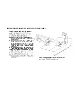
Page 10: ...guides Loosen belt keeper by loosening the two rear engine mount bolts this will allow belt to be placed on motor pulley Retighten engine mount bolts 6 Attach stabilizer arms to pivot point on the ins...

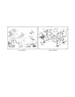
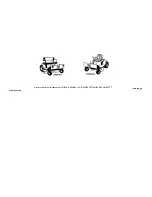
Page 11: ...BODY ASSEMBLY CHASSIS ASSEMBLY...

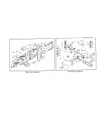
Page 12: ...MOWER DECK ASSEMBLY TRANSAXLE ASSEMBLY...

Page 13: ...581 Brake Pedal Arm 75 Model 1584 Brake Pedal 75 Model 3025 1 4 x 1 Spiral Pin 3026 1 4 x 1 1 2 Spiral Pin 3029 Front Grommet 3030 Rear Grommet 3054 3 16 x 1 Roll Pin 3070 1 4 x 1 1 4 Spiral Pin 3501...

Page 14: ...g 5025 Frame Assembly 5028 Bearing 5028 A Bearing Notched 5035 Transaxle Pulley 5036 Pivot Spring 5044 Torque Rod Stiffner Kit 5050 Positive Neutral Kit 6025 Mower Deck Assembly 6050 Mower Deck Weldme...

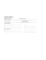
Page 15: ..._ Transaxle Serial Number_______________________ Oil changed this date 1 _______________________________________ 2 _______________________________________ 3 _______________________________________ Eng...

Page 16: ...Dixon and ZTR are the trademarks of Dixon Industries Inc Box 494 Coffeyville Kansas 67337 LITHO IN U S A FORM NO 812 476...

Reviews: