background image

ing rope  as soon as engine starts. To stop engine turn key 

to "OFF" position.


5. Set engine to desired speed by adjusting throttle control. 

(Suggest set at slow speed during initial operation.)


6. NOTE SAFETY FEATURE: Engine stops automatically if 

operator leaves seat while blades are engaged.


7. This unit is equipped with a unique transaxle that requires 

only two drive levers to control braking, turning, direction 

and acceleration. TO GO FORWARD:


From neutral position push both drive levers slightly for-

ward; to increase speed move levers further forward. TO 

GO BACKWARD:


From neutral position pull both drive levers slightly 

rearward. TURNING:


Turning is controlled by moving one drive lever slightly 

forward or rearward of the other. To turn left, move left 

lever rearward of right lever. To turn "square corners" move 

lever of desired direction to neutral. To turn on  mower's 

own axis (Zero radius) reduce speed and move one lever to 

reverse position and the other to forward position.


BRAKING:


To brake mower, move both levers in direction opposite of 

travel, release levers to neutral, set parking brake. When 

stopping on incline, it may be necessary to hold slight 

pressure on levers in direction opposite of slope, until 

parking brake is set.


ALWAYS SET PARKING.BRAKE BEFORE DISMOUNTING.


INITIAL OPERATION:


It is recommended that first operation of mower be done at 

a slow setting of throttle speed and disengagement of 

mower blades until operator is thoroughly familiar with  the 

unit.


You may have tendency to "over control" mower at first. 

Slight movements — fingertip control — is all that's 

necessary for easy operation. 8. Mower Blade Operation:


• Cutting height is set by positioning the adjustment lever. 

Push button knob on top of lever, set desired cutting 

height, lock into position by releasing button knob.


• To start mower blades, move lever on floor to "engage" 

position. To stop mower blades, move lever to "disen-

gage" position.


Summary of Contents for ZTR421, ZTR422, ZTR423

Page 1: ...OPERATOR S MANUAL FOR ZTR 421 422 423 MOWER...

Page 2: ...irs done outside the factory or authorized service stations nor does it obligate us to assume any transportation charges in connection with the replacement of parts claimed to be defective Our warrant...

Page 3: ...ly familiar with the controls Your Dixon dealer will gladly provide a check out ride and answer any questions READ CAREFULLY You have purchased a top quality lawn mower that has been inspected at the...

Page 4: ...g neighbors But when mowing all persons especially children and pets should be cleared from the mowing area 2 Wear appropriate safe clothing when mowing close fitting jeans or slacks and heavy leather...

Page 5: ...awn mower by the body lift only by the frame ALWAYS SET PARKING BRAKE AND DISENGAGE BLADE OPERATION BEFORE DISMOUNTING IMPORTANT OPERATING INSTURCTIONS Dixon ZTR mowers offer a new concept in mowing p...

Page 6: ...n on mower s own axis Zero radius reduce speed and move one lever to reverse position and the other to forward position BRAKING To brake mower move both levers in direction opposite of travel release...

Page 7: ...y be sure the battery is filled to proper fluid level with electrolite solution After initial filling level may be retained with distilled water CAUTION 5 During initial Break In period the oil level...

Page 8: ...When reinstalling the two screws in transaxle body mount make certain brake arm retainer clips extend downward and are parallel with body mount B ZTR 422 Body Removal 1 Disconnect throttle cable from...

Page 9: ...th a mild detergent and waxed with any automotive type wax ENGINE Follow the manufacturer s instructions as to maintenance and repair TRANSAXLE For adjustment or repair confer with authorized Dixon de...

Page 10: ...guides Loosen belt keeper by loosening the two rear engine mount bolts this will allow belt to be placed on motor pulley Retighten engine mount bolts 6 Attach stabilizer arms to pivot point on the ins...

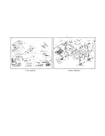
Page 11: ...BODY ASSEMBLY CHASSIS ASSEMBLY...

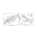
Page 12: ...MOWER DECK ASSEMBLY TRANSAXLE ASSEMBLY...

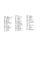
Page 13: ...581 Brake Pedal Arm 75 Model 1584 Brake Pedal 75 Model 3025 1 4 x 1 Spiral Pin 3026 1 4 x 1 1 2 Spiral Pin 3029 Front Grommet 3030 Rear Grommet 3054 3 16 x 1 Roll Pin 3070 1 4 x 1 1 4 Spiral Pin 3501...

Page 14: ...g 5025 Frame Assembly 5028 Bearing 5028 A Bearing Notched 5035 Transaxle Pulley 5036 Pivot Spring 5044 Torque Rod Stiffner Kit 5050 Positive Neutral Kit 6025 Mower Deck Assembly 6050 Mower Deck Weldme...

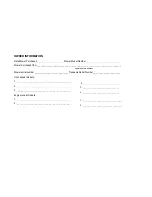
Page 15: ..._ Transaxle Serial Number_______________________ Oil changed this date 1 _______________________________________ 2 _______________________________________ 3 _______________________________________ Eng...

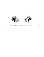
Page 16: ...Dixon and ZTR are the trademarks of Dixon Industries Inc Box 494 Coffeyville Kansas 67337 LITHO IN U S A FORM NO 812 476...

Reviews: