background image

©

 2014 DJI. All Rights Reserved. 


9

DJI DROPSAFE 

User Manual

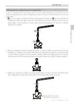
4.  Screw your ISI 16g CO

2

 canister into the mounting 

hole on the manifold.

Setting Up the CO

2

 Canister

Installing System Base

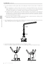
3.  Slide the safety pin into the hole on the side strip, 

and thread it through the hole on the system base. 

Be aware that the safety pin should always be 

placed through the strip that is located behind the 

system LED window. 

Safety Pin Hole

System LED 

Window

2.  Attach the three side strips onto the housing. 

1. Position the parachute housing over the system 

base, and gently slide the housing into place over 

the three arms of the manifold. Ensure that the 

LED window is aligned with the system LEDs.

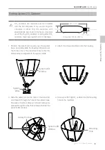
90±2 mm

10±1 mm

Screw size: 3/8 24 UNF-1A

System LED 

Window

System 

LEDs

Mounting 

Hole

CO

2

 canisters are required and not included 

with the DJI Dropsafe. Only use ISI 16g CO

2


canisters or other 16g CO

2

 canisters with 

specifications as shown in the figure. Improper 

use of the 16g CO

2

 canisters, or using other CO

2


canisters, may cause system error or damage.

Summary of Contents for Dropsafe

Page 1: ...DJI DROPSAFE 2014 12 V1 0 User Manual...

Page 2: ...DJI Dropsafe System 6 Detach System Base 6 Attachment Pad 6 Configure Remote Controller Switches 6 System Base Connection 6 Setting Up the System Base for Deployment 7 Setting Up the CO2 Canister 9 F...

Page 3: ...the tutorial videos below to learn how to use DJI Dropsafe correctly and safely www dji com product dropsafe video DJI Dropsafe official tutorial videos Profile The DJI Dropsafe is designed to reduce...

Page 4: ...ual Winglet x3 Side Strip x3 System Base x1 Including spring and triggering pin Manifold x1 Packing Tool x1 Connection Cable x4 Safety Pin x1 Trigger Compression Tool x1 Hex Screwdriver x1 Attachment...

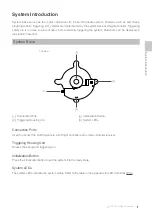
Page 5: ...e system Parachute can be deployed in less than 0 5 second System Base 1 Connection Ports 2 Triggering Housing Unit 3 Initialization Button 4 System LEDs Connection Ports Used to connect the DJI Drops...

Page 6: ...For A2 flight control system connect the ECO and WK ports on the system base to the X3 and F4 ports on your flight controller Then connect the RC2 port on the system base to the port on the RC receive...

Page 7: ...icators on system base will blink red and green for three times to indicate the system is functional 3 Rotate the screwdriver to tighten the trigger compression tool until the system LED blinks solid...

Page 8: ...place and system is connected with flight controller Unscrew the trigger compression tool for one round do not unscrew for more than one round otherwise triggering pin might be damaged when it is rel...

Page 9: ...Hole System LED Window 2 Attach the three side strips onto the housing 1 Position the parachute housing over the system base and gently slide the housing into place over the three arms of the manifol...

Page 10: ...opening of the parachute Ensure each short string is aligned with each of the three arms of the manifold 2 Start folding the parachute and put the packing tool in place The packing tool should cover...

Page 11: ...osition as circled below S1000 users can secure each connection string in the same locations Installing System Base 2 For example S900 users should connect and secure each connection string to its spe...

Page 12: ...e LEDs will display solid green and blink red for nine seconds During this period the DJI Dropsafe will not respond to any commands from the remote controller The system will only respond to commands...

Page 13: ...r flight controller safety function is active Blinking green The trigger is compressed and the remote controller or flight controller safety function is active Solid green and red Successful deploymen...

Page 14: ...http www dji com product dropsafe User manual is subject to change without prior notice You may visit DJI offical website to obtain the latest version of user manual 2014 DJI All Rights Reserved...

Reviews: