16
©2014 DJI. All Rights Reserved.
Zenmuse Z15-BMPCC
User Manual
GCU Ports Indication
The following table shows the GCU channels and TX channels connection.
TX Channels
GCU
Channels
Indications
JR
Futaba/Hitec
AILE
1
ROLL
Roll axis control (left/right). Velocity is zero if no input provided.
ELEV
2
TILT
Tilt axis control (front/back). Velocity is zero if no input provided.
RUDD
4
PAN
Pan axis control. Velocity is zero if no input provided.
AUX2
7
MODE
Working Mode switch.
----
SHUT
Reserved channel.
3-position switch channel
AUX1
Camera aperture adjust.
2-position switch channel
or Futaba S-Bus channel
AUX2
When the AUX2 port is connected to a 2-position switch channel,
it is used as camera orientation (down or forward) switch in FPV
(Reset). The camera orientation is forward when not connected or
no input is provided.
If S-Bus receiver is used, it should be connected to the AUX2 port.
2-position switch channel
or PPM channel
AUX3
Camera record control. Default is off when not connected or no
input is provided.
If a PPM receiver is used, it should be connected to the AUX3
port.
The following table shows the corresponding relationship between the GCU and the S-Bus/PPM
channels.
S-Bus/PPM Channels
GCU Channels
S-Bus/PPM Channels
GCU Channels
1
ROLL
5
SHUT
2
TILT
8
AUX1
4
PAN
3
AUX2
7
MODE
6
AUX3
Working Modes/AUX1/AUX2 Switch Settings
Working Mode Switch Settings
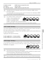
Whichever 3-position switch is selected as the working mode switch, wire the correct channel from
the receiver to the MODE port. At each switch position, use end-point fine tuning to set channel
AUX2(JR)/7(Futaba/Hitec) for the three Working modes.
W
orking Modes/AUX1/AUX2 Switch Settings
Summary of Contents for Zenmuse Z15-BMPCC
Page 1: ...Zenmuse Z15 BMPCC 2014 05 V1 0 User Manual ...
Page 27: ......


