background image

6

INSTRUCTIONS

SYSTEM OVERVIEW

If necessary, contact your local Customer Service representative for assistance setting up, using or maintaining the device, or to report unexpected operation or events.

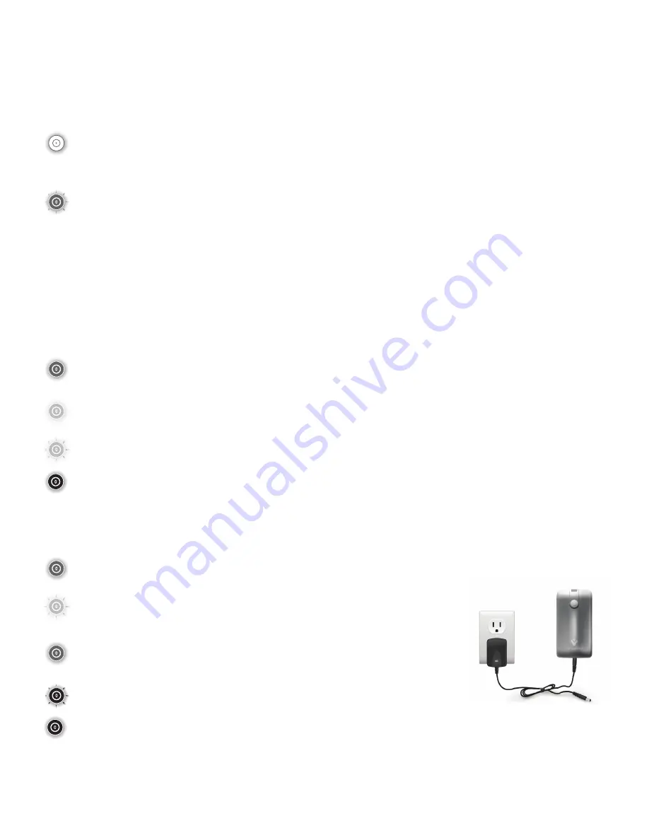
POWER OFF:

Unit is in “sleep” mode.  No visible LED illumination.

POWER ON:

Unit powers up with GREEN LED illuminated (flashing GREEN if connected to charger and battery is charging, or YELLOW can be illuminated if battery is LOW). After a 5 second delay, the 
pumps will allow inflation of the attached wrap to a pre-determined pressure of 50 mmHg.  Once the pressure reaches the proper level, the pump will enter a 50 second “rest” period, and the 
cuff deflates through the vent port to cool the leg or legs.  After the “rest” period, the wrap is again inflated, and so on every 50 seconds.

For Prescribing Physician Only:

Unit use time (amount of time the unit is powered ON) is monitored and stored by the MPU (Microprocessor Unit) and can be downloaded via the USB interconnecting to an interface module. 

BATTERY INDICATOR

In order to properly indicate the state of the battery and charger, there are THREE stages of the BATTERY INDICATOR as follows:

 STAGE 1 – GREEN:


When the unit power is ON 

and the battery is charging, the GREEN LED flashes.  A steady GREEN LED indicates battery is fully charged (if  


connected to charger) or has adequate power for portable operation if not connected to charger.

 STAGE 2 – YELLOW:


The yellow LOW BATTERY INDICATOR will REMAIN ILLUMINATED during the pumping time and rest period. At this stage the battery charger MUST be  


connected immediately to avoid any interruption in the treatment sessions.

 FLASHING YELLOW: 

 I

f the battery voltage drops below a critical level at any time, while unit is ON, flashing yellow and audible alarm beeps for 30 seconds.  Unless unit is    


turned off OR connected to charger within that 30 seconds, unit WILL AUTOMATICALLY power OFF.

 STAGE 3 – RED: 


When the unit is turned OFF and the battery is charging, the RED LED FLASHES. Once the battery reaches full charge, the RED LED REMAINS SOLID. 

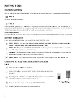
USING THE AC ADAPTER AND BATTERY CHARGER

POWER

 If the power button illuminates GREEN the units are fully operational.

 If the devices DO NOT turn ON, or the power button is “YELLOW” or “FLASHING YELLOW” plug in the power cord immediately to the    


electrical outlet.

 IF units are plugged in, AND turned ON the power button will either FLASH GREEN (showing the batteries are being charged) or illuminate  


SOLID GREEN (showing batteries have reached adequate charge for portable operation).

 When the unit is turned OFF and plugged in the battery is charging and POWER BUTTON FLASHES RED.

 Once the battery reaches full charge the POWER BUTTON WILL BE RED and REMAIN SOLID.

Summary of Contents for VenaPRo

Page 1: ...Vascular Therapy System Compressible Limb Sleeve Device 30MI Enhancing Life Through Innovation Instructions for Use ...

Page 2: ...STORAGE 8 DISPOSAL 8 COMPLIANCE STATEMENTS 9 ELECTROMAGNETIC COMPATIBILITY EMC 9 ELECTROMAGNETIC COMPATIBILITY EMC TABLES RF EMISSIONS CLASS B 9 GUIDANCE AND MANUFACTURER S DECLARATION ELECTROMAGNETIC EMISSIONS 9 GUIDANCE AND MANUFACTURER S DECLARATION ELECTROMAGNETIC IMMUNITY 10 GUIDANCE AND MANUFACTURER S DECLARATION ELECTROMAGNETIC IMMUNITY 11 RECOMMENDED SEPARATION DISTANCES BETWEEN PORTABLE A...

Page 3: ... limbs As prophylaxis for DeepVeinThrombosis DVT by persons expecting to be stationary for long periods of time CONTRAINDICATIONS TheVenaPro MUST NOT be used to treat the following conditions Persons with suspected active or untreated deep vein thrombosis ischemic vascular disease severe arteriosclerosis pulmonary edema severe congestive heart failure thrombophlebitis or an active infection On the...

Page 4: ...es If you believe interference is occurring please consult Electromagnetic Compatibility EMC section To prevent extremity compartment syndrome special attention should be given to patients who are positioned in the supine lithotomy position for extended lengths of time This includes patients with or without cuffs Cuffs used in combination with warming devices may cause skin irritation Regularly ch...

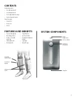
Page 5: ... Easy one touch operation No restricting air hoses Air releases to cool the patients leg Soft breathable cuffs Battery Operated Single Patient Use Low Pressure Alarm Downloadable Compliance Monitor Lightweight Compact Design Downloadable Compliance Monitor Air Releases to Keep Leg Cool Easy OneTouch Operation Low Pressure Indicator USB Port for physician use Power Button Battery Indicator Charging...

Page 6: ...harging the GREEN LED flashes A steady GREEN LED indicates battery is fully charged if connected to charger or has adequate power for portable operation if not connected to charger STAGE 2 YELLOW The yellow LOW BATTERY INDICATOR will REMAIN ILLUMINATED during the pumping time and rest period At this stage the battery charger MUST be connected immediately to avoid any interruption in the treatment ...

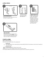
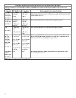
Page 7: ...ngandsqueezingyourleg THIS IS NORMAL Thewrapswill inflateonceaminute IFyouFEELairreleasingaroundthelegs this isnormal Thisisafunctionof thedevicetokeepyourlegscool 4 PUMP ALARMS What to do if the Pump Alarms Don t worry the alarms are there to ensure the units are operating correctly BATTERY CRITICAL Ifbatteryvoltagedropsbelowacriticallevel cyclingstops audiblealarmwillsound andUNITWILLFLASHYELLOW...

Page 8: ...any damage is noticed Avoid subjecting the units to shocks such as dropping the pumps Do not handle the leg cuffs with any sharp objects If a bladder is punctured or you notice a leak do not attempt to repair the unit or cuffs Replacement units are available through customer service Avoid folding or creasing the bladder during use and transportation of the units Battery is not replaceable replacem...

Page 9: ... control such as paging systems Label devices susceptible to EMI Educate clinical staff to recognize potential EMI related problems Eliminate or reduce EMI with technical solutions such as shielding Restrict use of personal communicators cell phones computers in areas with devices susceptible to EMI Share relevant EMI information with others particularly when evaluating new equipment purchases whi...

Page 10: ...e 2kV common mode 1kV differential mode 2kV common mode Mains power quality should be that of a typical commercial or hospital environment Voltage dips short interruptions and voltage variations on power supply input lines IEC 61000 4 11 5 UT 95 dip in UT for 0 5 cycle 40 UT 60 dip in UT for 5 cycles 70 UT 30 dip in UT for 25 cycles 5 UT 95 dip in UT for 5 sec 5 UT 95 dip in UT for 0 5 cycle 40 UT...

Page 11: ...y To assess the electromagnetic environment due to fixed RF transmitters an electromagnetic site survey should be considered If the measured field strength in the location in which theVenaPro is used exceeds the applicable RF compliance level above theVenaPro should be observed to verify normal operation If abnormal performance is observed additional measures may be necessary such as reorienting o...

Page 12: ...PUT Mode of Operation Continuous SYSTEM OPERATING ENVIRONMENT Temperature 5 C 41 F and 40 C 104 F Relative Humidity 15 93 Atmospheric Pressure 525mmHg to 795mmHg Altitude below 3000 m DEFAULT SETTINGS Leg Pressure not adjustable 50 mmHg Cycle time 60 Seconds TOLERANCES Pressure 5 BATTERY This device is powered by internal Li ion batteries BATTERY CHARGE Takes approximately 4 hours from depleted st...

Page 13: ...d Perungudi Chennai 600 096 India Tel 91 44 66915127 Email customercare india DJOglobal com ITALY DJO Italia Srl Via Leonardo DaVinci 97 Trezzano Sul Naviglio 20090 Milano Italy Tel 39 02 484 63386 Fax 39 02 484 09217 Email vendite djoglobal com SOUTH AFRICA DJO South Africa Pty Ltd Unit 1 Brackengate Business Park 5 on London Brackenfell 7560 CapeTown South Africa Tel 27 21 706 16 88 Email info s...

Page 14: ...MDSS GmbH Schiffgraben 41 30175 Hannover Germany DJO LLC 1430 Decision Street Vista CA 92081 8533 USA DJOglobal com 30M100_A Raising the Standard of DVT Prevention ...

Reviews: