MSD600M - Technical Reference Manual
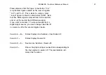
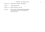
Please observe that the figure in illustration ”C+4”
is a phantom figure created as the sum of signals
”C+3” and ”C+5”. This is done to create a more
“round” figure as shown in illustration ”SUM”. Note
that this SUM signal is derived from CH5 and CH6
and is not the normal Sum/Difference signal.
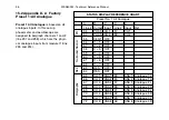
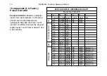
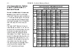
If you want to monitor 7.1 surround sound from a
digital signal source, you must change lines #65-72
in column A+B to the relevant digital inputs.
51
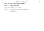
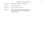
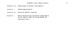
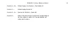
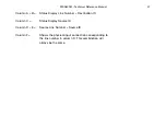
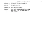
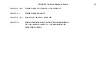
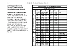
Column A + B =
Status Display Line Destination ID
Column C =
Status Display Source ID
Column D + E =
Source Line Source ID
Column F =
Shows the physical input connection corresponding to
the line number in column D. This combination will
always be the same.
Summary of Contents for MSD600M
Page 7: ...MSD600M Technical Reference Manual 3...
Page 9: ...MSD600M Technical Reference Manual 5 See notes opposite page...
Page 11: ...MSD600M Technical Reference Manual 7...
Page 17: ...MSD600M Technical Reference Manual 13...
Page 23: ...MSD600M Technical Reference Manual 19...
Page 26: ...22 MSD600M Technical Reference Manual 10 The DK SCALE PC Software Program...
Page 33: ...MSD600M Technical Reference Manual 29...
Page 34: ...30 MSD600M Technical Reference Manual 13 Appendix B Mechanical Dimensions...
Page 35: ...MSD600M Technical Reference Manual 31...
Page 39: ...MSD600M Technical Reference Manual 35...

