Installation
PTV
PT 5201
Revision 2
Operating Manual
5-2
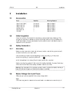
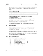
This instrument is equipped with a tap-less switch mode power supply that covers most nominal
voltage ranges in use: 90-250V AC RMS. This obviates the need to adapt to the local mains
voltage.
The mains frequency is 47-63 Hz.
Warning
: This instrument is intended not to have the fuse renewed. If the fuse is damaged the
power supply unit is also affected.
If the mains power supply has to be replaced please proceed as follows:
1. Remove the mains cable
2. Unscrew all 11 screws of the top cover
3. Disconnect the power connector from the main PCB and the internal ground cable from the
chassis
4. Unbolt the power inlet from the rear panel and the PCB from the chassis stand-off’s
5. Replace power supply unit and assemble in reverse order
The power supply is a safety and service part. The ordering number is 4008 109 86650
5.5
Rack Mounting
The PT 5201 Compact Varitime™ Sync Generator is in a half size 19” rack cabinet. The
instrument is intended for rack mounting as well as desktop use. A rack mount kit for
conventional 19” rack is included.
When the Sync Generator is used in desk top applications PTV recommend the mounting of the
four self-adhesive rubber feet, included in the rack mount kit.
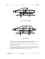
The included rack mount kit features ability to mount one or two units in a 19” rack system. The
rack mount instruction, see below, specifies the parts.
5.5.1
Rack Mount Instructions
The PT 5201 is delivered with the following mounting parts:
1 pc.
Side bracket
1 pc.
Blind plate including rack mount ear
2 pc.
Support base plates
4 pc
Pan head screws M2.5x6
B
8 pc.
Countersink screws M2.5x6
A
4 pc.
Pan head screw M6x16 for rack frame
4 pc.
Rack frame clips/nuts M6
4 pc.
Rubber feet (for table top use)
Summary of Contents for PT 5201 Compact VariTime
Page 6: ......
Page 20: ......
Page 40: ......
Page 56: ......
Page 63: ...PT 5210 PTV Operating Manual Revision 2 11 5 END OF DOCUMENT ...


