Operating Instructions
PTV
PT 5201
Revision 2
Operating Manual
6-2
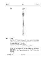
PRESET selection:
Impact to PRESET
button
PRESET status
Indication on LEDs
A short press
Indicates active PRESET
One pair or no LED pair lit in 2 sec.
Hold for 3 sec. or more.
Scrolling through the
PRESETs.
Stop when selected preset has
been reached
LED pairs are scrolling
Hold for 20 sec.
FACTORY PRESET is loaded
After scrolling 3 times through all
pairs, all LEDs are lit
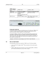
Front panel connector
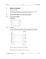
The front panel connector is intended to interface the unit to PC control using a COM port. The
connector is a D-SUB 9 pole male configured for RS232 communication based on SCPI
protocol. See chapter 7 Remote Interface for a technical description.
Connecting the interface cable from the PC to the unit special attention must be paid to the
power source of both parties. When the controlling PC is mains power operated the ground
potential of the mains power supply for both instruments has to be taking in consideration. To
reduce problems concerning different mains power ground potential both instruments need to
have common mains power source.
Negligence of this matter can cause damages to the PT 5201 or the PC COM port
6.3
How to Get Started
These instructions tell you how to connect your PT 5201 to your PC for the very first time.
1. Connect the PT 5201 Compact VariTime
TM
Sync Generator unit to the mains using the
power cord.
2.
Using the interface cable connect PT 5201 to your PC by selecting COM1 (or COM2) on
your PC and the D-SUB connector on the PT 5201 front panel.
Summary of Contents for PT 5201 Compact VariTime
Page 6: ......
Page 20: ......
Page 40: ......
Page 56: ......
Page 63: ...PT 5210 PTV Operating Manual Revision 2 11 5 END OF DOCUMENT ...

