MSD/PT0600/200 - Technical Reference Manual
25
13. Pin Configuration
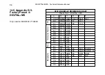
13.1 Appendix C-1.
Pin configuration for VGA and
Utility DSUB Connector
The pin configuration of the VGA and the Utility
connector is common for all supported models.
VGA
15-Pole DSUB
GND
Pin 5,6,7,8,10
H-sync
Pin 13
V-sync
Pin 14
Red
Pin 1
Green
Pin 2
Blue
Pin 3
Power , RS232 & I2C
9-Pole DSUB
+Vcc
12-15V
Pin 4
Power ground
Pin 5
I2C
IRQ
Pin 8
SDA
Pin 7
SCL
Pin 6
RS232
TX
Pin 2
RX
Pin 3
GND
Pin 1
Summary of Contents for PTO200C
Page 6: ...MSD PT0600 200 Technical Reference Manual...
Page 21: ...MSD PT0600 200 Technical Reference Manual 15 9 The DK SCALE PC Software Program...
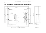
Page 30: ...MSD PT0600 200 Technical Reference Manual 24 Rear view Chassis for the PT0600 200...
Page 69: ...MSD PT0600 200 Technical Reference Manual 63...
Page 73: ...MSD PT0600 200 Technical Reference Manual 67...

