background image

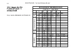
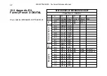
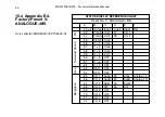
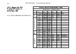
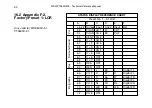
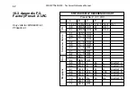
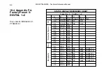
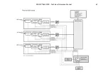
STATUS DISPLAY REFERENCE CHART

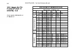
Preset No. 3 - DIGITAL 1+2

A

B

C

D

E

F

Line # Output Input

Line # Input

Ref.

53

PHAS

CH 1

57

CH 1

54

PHAS

CH 2

58

CH 2

55

CENT

OFF

56

C + 1

OFF

57

C + 2

OFF

58

C + 3

OFF

59

C + 4

OFF

60

C + 5

OFF

61

C + 6

OFF

62

C + 7

OFF

63

RES

OFF

64

RES

OFF

65

CH 1

Aes1

35

Aes1

Digital 1 L

66

CH 2

Aes2

36

Aes2

Digital 1 R

67

CH 3

Aes3

37

Aes3

Digital 2 L

68

CH 4

Aes4

38

Aes4

Digital 2 R

69

CH 5

Aes5

39

Aes5

Digital 3 L

70

CH 6

Aes6

40

Aes6

Digital 3 R

71

CH 7

OFF

72

CH 8

OFF

MSD/PT0600/200 - Technical Reference Manual

54

16.4 Appendix F-4. 
Factory Preset 3: 
DIGITAL 1+2

Only valid for: MSD600C-5.1, 
PT0600C-5.1

Bar

graphs

Res.

Surr

ound Sound       PH

Summary of Contents for PTO200C

Page 1: ...udio com MSD PT0600C 5 1 MSD PT0600C III MSD PT0200C MASTER STEREO DISPLAY Technical Reference Manual interstage Phistersvej 31 2900 Hellerup Danmark Telefon 3946 0000 fax 3946 0040 www interstage dk...

Page 2: ...written consent from DK Audio A S Trademarks Analog Devices is a registered trademark of Analog Devices Inc USA Crystal is a registered trademark of Cirrus Logic Inc USA AKM is a registered trademark...

Page 3: ...Output 5 4 4 Digital Audio Output 6 4 5 External Sync Source Input 6 4 6 DSP Microcomputer 6 4 7 Flash PROM Program Storage Media 7 4 8 LCD Display 7 4 9 Hardware ID 7 4 10 Power Supply 8 Section Page...

Page 4: ...Preset 0 BASE SETUP 48 16 2 Appendix F 2 Factory Preset 1 LCR 50 16 3 Appendix F 3 Factory Preset 2 LRC 52 Contents Section Page 13 Appendix C Pin Configuration 25 13 1 Appendix C 1 Pin configuration...

Page 5: ...ndix F 6 Factory Preset 5 DIGITAL 5 6 58 17 Appendix G Audio Matrix Flow Charts 60 17 1 Appendix G 1 MSD PT0200C 60 17 2 Appendix G 2 MSD PT0600C III 61 17 3 Appendix G 3 MSD PT0600C 5 1 62 18 Appendi...

Page 6: ...MSD PT0600 200 Technical Reference Manual...

Page 7: ...you to receive up to date informa tion from DK Audio on future Master Stereo Display products Please also check our website at www dk audio com 1 1 This Manual This manual is an addendum to the Softw...

Page 8: ...put including separate Left Right channels of an AES 3 stream Any function on the MSD is treated as an Output and is assigned an input from the Audio Matrix just like any other physical Output source...

Page 9: ...ion please see sec tion 8 2 4 1 SRC Bypass and external sync in the software manual It is normal that professional audio equipment such as mixing consoles are fitted with sample rate converters in the...

Page 10: ...en using the MSD with one of the DMU scales which are true peak scales it is recommended that the MSD SRC s used are in Bypass mode The rea son is that the SRC under certain situations effects the pea...

Page 11: ...o Input circuit designed around the Cirrus Logic AES 3 receiver chip the CS8420 This AES 3 receiver has not only become an indu stry standard but also contains the Sample Rate Converter SRC used by th...

Page 12: ...n AES 3 input sig nal of any arbitrary sample rate between 32 kHz to 96 kHz and convert it to the internal used sample rate 4 5 External Sync Source Input All supported MSD models are able to use any...

Page 13: ...CCFT installed inside the unit for background illumination with an expected lifetime of approximately 50 000 hours The display is controlled directly from the DSP using a Display Driver design develop...

Page 14: ...0242 MSD600C III PT0600C III 0263 MSD600C 5 1 PT0600C 5 1 0253 MSD600M 0100 not covered by this manual Under normal conditions the user should not be concerned about the function of this ID 4 10 Power...

Page 15: ...e visit our homepage at www dk audio com for more information regarding this extension bracket The remaining three MSD models are designed to fit into the supplied free standing mounting brac ket maki...

Page 16: ...nger screws Insert the supplied star washers between the bracket and cabinet This allows the MSD to be turned both horizontally and vertically for the best viewing angle Mounting the MSD only allowing...

Page 17: ...The breakout cables have all the necessary DSUB connectors to XLR audio in out connectors Diagrams for all available breakout cables are avail able on our web site www dk audio com Detailed informati...

Page 18: ...polarizer is very soft and easily scratched only use a soft dry cloth without chemicals for cleaning Do not allow water or liquids to remain on the surface for long This may cause local defor mation...

Page 19: ...sets is using the Analogue Digital output Below is listed a factory preset selection chart for all the supported MSD models Supported Model MSD200C MSD600C III PT0200C PT0600C III Preset Preset Name D...

Page 20: ...setting and can be user changed by special procedure only Dig 1 5 1 LCR 5 1 Surround Sound Left Centre Right Dig 2 5 1 LRC 5 1 Surround Sound Left Right Centre Dig 3 DIGITAL 1 2 All Digital Input Vec...

Page 21: ...MSD PT0600 200 Technical Reference Manual 15 9 The DK SCALE PC Software Program...

Page 22: ...giving the user the freedom of choos ing specific scales from the library it also gives the opportunity to design your own scale The DK Scale program is a DOS program but can be run from inside a DOS...

Page 23: ...2 If a COM port has not been set the update program will abort The command SET MSD LOAD is valid only for the actual DOS box This means that the update program must be executed from the same DOS box...

Page 24: ...ms Return fallback time Pflichtenhft 3 6 20 dB 1 5 s IEC 268 10 20 dB 2 0 s Division of scales More scales are available through the DK scale program Type I 42 dB to 12 dB Type IIA 1 dB to 7 dB Type...

Page 25: ...s PT 19 Rack versions Width 214 mm Height 133 mm Depth 41 mm Power Supply Supply Voltage range 12 24V DC DC Power consumption Approx 18 W 12V nominal supply Safety according to IEC 65 LCD Display Reso...

Page 26: ...0 002dB Group Delay 0 82 mSec Dynamic Range 103 dB A Weighted Cross Talk 96 dB 1 kHz S N D 1 dBFS typ 93dB Nominal Input impedance 20 kOhm Analogue Output 1 Maximum Output Level 18 dBm 600 Ohm Sample...

Page 27: ...nce 110 Ohm Typical Nominal Output Impedance 110 Ohm Typical 1 Measured with default condition at 48 kHz internal sample rate Used unless other is mentioned 2 Measured with default condition at 48 kHz...

Page 28: ...MSD PT0600 200 Technical Reference Manual 22 12 Appendix B Mechanical Dimensions Rear view Chassis for the MSD600 200 Side view...

Page 29: ...MSD PT0600 200 Technical Reference Manual 23 Side view Rack mounting chassis for the PT0600 200...

Page 30: ...MSD PT0600 200 Technical Reference Manual 24 Rear view Chassis for the PT0600 200...

Page 31: ...nector The pin configuration of the VGA and the Utility connector is common for all supported models VGA 15 Pole DSUB GND Pin 5 6 7 8 10 H sync Pin 13 V sync Pin 14 Red Pin 1 Green Pin 2 Blue Pin 3 Po...

Page 32: ...DSUB connector Analogue AES 3 Input Output MSD200C and PT0200C 25 Pole DSUB Input ANA 1 Hot Pin 14 Cold Pin 1 GND Pin 2 ANA 2 Hot Pin 15 Cold Pin 3 GND Pin 16 AES 3 1 Hot Pin 9 Cold Pin 21 GND Pin 22...

Page 33: ...Pole DSUB Input ANA 1 Hot Pin 14 Cold Pin 1 GND Pin 2 ANA 2 Hot Pin 15 Cold Pin 3 GND Pin 16 AES 3 1 Hot Pin 9 Cold Pin 21 GND Pin 22 AES 3 2 Hot Pin 10 Cold Pin 23 GND Pin 22 Output ANA 1 Hot Pin 17...

Page 34: ...B C D E F Line Output Input Line Input Ref 53 PHAS CH 1 57 CH 1 54 PHAS CH 2 58 CH 2 55 CENT CH 3 56 C 1 CH 2 57 C 2 CH 6 58 C 3 CH 5 59 C 4 CH 1 60 C 5 OFF 61 C 6 OFF 62 C 7 OFF 63 RES OFF 64 RES OF...

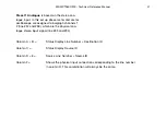
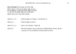
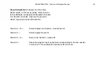
Page 35: ...ctory set up shown above monitors both the analogue and digital input The phase meter and vector oscilloscope is assigned to bargraph chan nels 1 2 line 57 and 58 Column A B Status Display Line Number...

Page 36: ...A B C D E F Line Output Input Line Input Ref 53 PHAS CH 1 57 CH 1 54 PHAS CH 2 58 CH 2 55 CENT CH 3 56 C 1 CH 2 57 C 2 CH 6 58 C 3 CH 5 59 C 4 CH 1 60 C 5 OFF 61 C 6 OFF 62 C 7 OFF 63 RES OFF 64 RES...

Page 37: ...to bargraph channels 1 2 line 57 and 58 which are the physical ana logue stereo input signal line 33 and 34 Column A B Status Display Line Number Destination ID Column C Status Display Source ID Colum...

Page 38: ...B C D E F Line Output Input Line Input Ref 53 PHAS CH 1 57 CH 1 54 PHAS CH 2 58 CH 2 55 CENT CH 3 56 C 1 CH 2 57 C 2 CH 6 58 C 3 CH 5 59 C 4 CH 1 60 C 5 OFF 61 C 6 OFF 62 C 7 OFF 63 RES OFF 64 RES OF...

Page 39: ...signed to bargraph channels 1 2 line 57 and 58 which are the physical AES 3 inputs line 35 and 36 Column A B Status Display Line Number Destination ID Column C Status Display Source ID Column D E Sour...

Page 40: ...C 3 CH 5 59 C 4 CH 1 60 C 5 OFF 61 C 6 OFF 62 C 7 OFF 63 RES OFF 64 RES OFF 65 CH 1 AnaL 33 AnaL Analog 1 L 66 CH 2 AnaR 34 AnaR Analog 1 R 67 CH 3 SUM 55 SUM 68 CH 4 DIF 56 DIF 69 CH 5 OFF 70 CH 6 O...

Page 41: ...ch are the physical ana logue stereo input signal line 33 and 34 The bargraph channel 3 4 is used to monitor the SUM and DIF signal of the MS measurement Column A B Status Display Line Number Destinat...

Page 42: ...F Line Output Input Line Input Ref 53 PHAS CH 1 57 CH 1 54 PHAS CH 2 58 CH 2 55 CENT CH 3 56 C 1 CH 2 57 C 2 CH 6 58 C 3 CH 5 59 C 4 CH 1 60 C 5 OFF 61 C 6 OFF 62 C 7 OFF 63 RES OFF 64 RES OFF 65 CH...

Page 43: ...ch are the physical AES 3 input signal line 33 and 34 The bargraph channel 3 4 is used to monitor the SUM and DIF signal of the MS measurement Column A B Status Display Line Number Destination ID Colu...

Page 44: ...ES OFF 64 RES OFF 65 CH 1 AnaL 33 AnaL Analog 1 L 66 CH 2 AnaR 34 AnaR Analog 1 R 67 CH 3 Aes1 35 Aes1 Digital 1 L 68 CH 4 Aes1 36 Aes1 Digital 1 R 69 CH 5 Aes2 37 Aes2 Digital 2 L 70 CH 6 Aes2 38 Aes...

Page 45: ...factory set up shown above monitors both the analogue and digital input The phasemeter and vector oscilloscope is assigned to bargraph chan nels 1 and 2 line 57 and 58 Column A B Status Display Line N...

Page 46: ...LOGUE A B C D E Line Output Input Line Input Ref 53 PHAS CH 1 57 CH 1 54 PHAS CH 2 58 CH 2 55 CENT CH 3 56 C 1 CH 2 57 C 2 CH 6 58 C 3 CH 5 59 C 4 CH 1 60 C 5 OFF 61 C 6 OFF 62 C 7 OFF 63 RES OFF 64 R...

Page 47: ...to bargraph channels 1 2 line 57 and 58 which are the physical ana logue stereo input signal line 33 and 34 Column A B Status Display Line Number Destination ID Column C Status Display Source ID Colum...

Page 48: ...AL A B C D E F Line Output Input Line Input Ref 53 PHAS CH 1 57 CH 1 54 PHAS CH 2 58 CH 2 55 CENT CH 3 56 C 1 CH 2 57 C 2 CH 6 58 C 3 CH 5 59 C 4 CH 1 60 C 5 OFF 61 C 6 OFF 62 C 7 OFF 63 RES OFF 64 RE...

Page 49: ...ed to bargraph channels 1 2 line 57 and 58 which are the physical AES 3 input pair 1 line 35 and 36 Column A B Status Display Line Number Destination ID Column C Status Display Source ID Column D E So...

Page 50: ...A B C D E F Line Output Input Line Input Ref 53 PHAS CH 1 57 CH 1 54 PHAS CH 2 58 CH 2 55 CENT CH 3 56 C 1 CH 2 57 C 2 CH 6 58 C 3 CH 5 59 C 4 CH 1 60 C 5 OFF 61 C 6 OFF 62 C 7 OFF 63 RES OFF 64 RES...

Page 51: ...ch are the physical ana logue stereo input signal line 33 and 34 The bargraph channel 3 4 is used to monitor the SUM and DIF signal of the MS measurement Column A B Status Display Line Number Destinat...

Page 52: ...B C D E F Line Output Input Line Input Ref 53 PHAS CH 1 57 CH 1 54 PHAS CH 2 58 CH 2 55 CENT CH 3 56 C 1 CH 2 57 C 2 CH 6 58 C 3 CH 5 59 C 4 CH 1 60 C 5 OFF 61 C 6 OFF 62 C 7 OFF 63 RES OFF 64 RES OF...

Page 53: ...58 which are the physical AES 3 input signal line 33 and 34 The bargraph chan nel 3 4 is used to monitor the SUM and DIF signal of the MS measurement Column A B Status Display Line Number Destination...

Page 54: ...C D E F Line Output Input Line Input Ref 53 PHAS CH 1 57 CH 1 54 PHAS CH 2 58 CH 2 55 CENT CH 3 56 C 1 CH 2 57 C 2 CH 6 58 C 3 CH 5 59 C 4 CH 1 60 C 5 OFF 61 C 6 OFF 62 C 7 OFF 63 RES OFF 64 RES OFF...

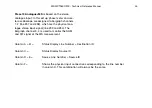
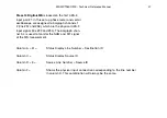
Page 55: ...From factory this preset will be equal preset 2 Preset can be user confi gured only by a special procedure Column A B Status Display Line Number Destination ID Column C Status Display Source ID Column...

Page 56: ...C 5 OFF 61 C 6 OFF 62 C 7 OFF 63 RES OFF 64 RES OFF 65 CH 1 L 35 L Digital 1 L 66 CH 2 C 37 C Digital 2 L 67 CH 3 R 36 R Digital 1 R 68 CH 4 Ls 39 Ls Digital 3 L 69 CH 5 Rs 40 Rs Digital 3 R 70 CH 6...

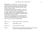
Page 57: ...ons this particular set up uses five vectors in order to show the surround sound information The CENT figure is coupled to the bargraph showing the centre information and vector C 1 is coupled to the...

Page 58: ...ut Line Input Ref 53 PHAS CH 1 57 CH 1 54 PHAS CH 2 58 CH 2 55 CENT CH 3 56 C 1 CH 2 57 C 2 CH 6 58 C 3 CH 5 59 C 4 CH 1 60 C 5 OFF 61 C 6 OFF 62 C 7 OFF 63 RES OFF 64 RES OFF 65 CH 1 L 35 L Digital 1...

Page 59: ...round information The CENT figure is coupled to the bargraph showing the centre information and vector C 1 is coupled to the bargraph showing the information from the right channel The next vectors ar...

Page 60: ...62 C 7 OFF 63 RES OFF 64 RES OFF 65 CH 1 Aes1 35 Aes1 Digital 1 L 66 CH 2 Aes2 36 Aes2 Digital 1 R 67 CH 3 Aes3 37 Aes3 Digital 2 L 68 CH 4 Aes4 38 Aes4 Digital 2 R 69 CH 5 Aes5 39 Aes5 Digital 3 L 7...

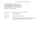
Page 61: ...ssigned to bargraph channels 1 2 line 57 and 58 which are the physical AES 3 input pair 1 line 35 and 36 Column A B Status Display Line Number Destination ID Column C Status Display Source ID Column D...

Page 62: ...Input Ref 53 PHAS CH 3 59 CH 3 54 PHAS CH 4 60 CH 4 55 CENT OFF 56 C 1 OFF 57 C 2 OFF 58 C 3 OFF 59 C 4 OFF 60 C 5 OFF 61 C 6 OFF 62 C 7 OFF 63 RES OFF 64 RES OFF 65 CH 1 Aes1 35 Aes1 Digital 1 L 66...

Page 63: ...ssigned to bargraph channels 3 4 line 59 and 60 which are the physical AES 3 input pair 2 line 37 and 38 Column A B Status Display Line Number Destination ID Column C Status Display Source ID Column D...

Page 64: ...e Input Ref 53 PHAS CH 5 61 CH 5 54 PHAS CH 6 62 CH 6 55 CENT OFF 56 C 1 OFF 57 C 2 OFF 58 C 3 OFF 59 C 4 OFF 60 C 5 OFF 61 C 6 OFF 62 C 7 OFF 63 RES OFF 64 RES OFF 65 CH 1 Aes1 35 Aes1 Digital 1 L 66...

Page 65: ...ssigned to bargraph channels 5 6 line 61 and 62 which are the physical AES 3 input pair 3 line 39 and 40 Column A B Status Display Line Number Destination ID Column C Status Display Source ID Column D...

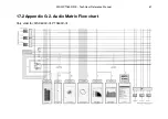
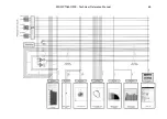
Page 66: ...MSD PT0600 200 Technical Reference Manual 60 17 Audio Matrix Flow Charts 17 1 Appendix G 1 Audio Matrix Flow chart Only valid for MSD200C PT0200C...

Page 67: ...MSD PT0600 200 Technical Reference Manual 61 17 2 Appendix G 2 Audio Matrix Flow chart Only valid for MSD600C III PT0600C III...

Page 68: ...MSD PT0600 200 Technical Reference Manual 62 17 3 Appendix G 3 Audio Matrix Flow chart Only valid for MSD600C 5 1 PT0600C 5 1...

Page 69: ...MSD PT0600 200 Technical Reference Manual 63...

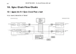
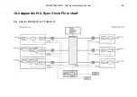
Page 70: ...MSD PT0600 200 Technical Reference Manual 64 18 Sync Clock Flow Charts 18 1 Appendix H 1 Sync Clock Flow chart Only valid for MSD200C PT0200C...

Page 71: ...MSD PT0600 200 Technical Reference Manual 65 18 2 Appendix H 2 Sync Clock Flow chart Only valid for MSD600C III PT0600C III...

Page 72: ...MSD PT0600 200 Technical Reference Manual 66 18 3 Appendix H 3 Sync Clock Flow chart Only valid for MSD600C 5 1 PT0600C 5 1...

Page 73: ...MSD PT0600 200 Technical Reference Manual 67...

Page 74: ...MSD PT0600 200 Technical Reference Manual 68...

Page 75: ...you may use this page instead Name Company Address Postcode City Country Phone Fax E mail Model No Unit Serial No Purchase Date Purchased from dealer Which features would you like to see in new versi...

Reviews: