background image


90 


to left 


● 


● 

● 


● 


● 


● 


● 

● 


● 

● 

● 


● 

● 


● 


● 


● 

● 

● 


● 


● 

● 

● 


● 

● 


● 

● 

● 

● 

● 

● 

● 

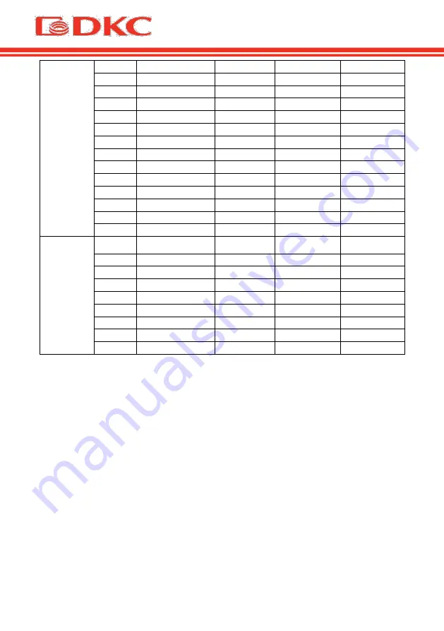
The fourth 
number 
(letter)  
from right 
to left 

Display 

value 

Over load fault 

Mains lost 

Bypass abnormal 


● 


● 


● 

● 


● 


● 


● 


● 

● 


● 

● 

● 


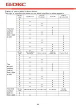
Table 14. Display of errors on the screen 

Example: 
If the alarm code "2000" appears on the LCD screen,  it indicates loss of mains 
power.


Summary of Contents for SMALLT1

Page 1: ...User s Manual Small Tower 1000 3000 Uninterruptible Power Supply Small Tower 1000 3000 VA...

Page 2: ......

Page 3: ...5 1 7 2 7 3 8 3 1 8 3 2 8 3 3 9 3 4 9 3 5 9 4 11 4 1 11 4 2 12 4 3 13 4 4 14 4 4 1 14 4 4 2 14 4 4 3 15 4 4 4 15 4 5 15 4 5 1 15 4 5 2 16 4 5 3 16 4 6 16 4 6 1 16 4 6 2 17 4 7 18 4 7 1 18 4 7 2 19 5 2...

Page 4: ...5 1 23 5 2 25 5 3 26 5 3 1 26 5 3 2 27 5 4 28 5 5 30 5 6 32 6 35 6 1 35 6 2 36 6 3 36 7 38 7 1 38 7 2 43 8 46 8 1 46 8 2 47 8 3 51 8 4 51 8 5 52 9 52...

Page 5: ...and modifications 60 4 2 Front view of the UPS 62 4 3 Typology 62 4 4 System Description 63 4 4 1 Rectifier 63 4 4 2 Invertor 63 4 4 3 Batteries and Battery Charger 64 4 4 4 Bypass 64 4 5 Operating st...

Page 6: ...tion 78 5 6 UPS Settings 80 6 Maintenance 83 6 1 Verifying UPS operation 83 6 2 UPS maintenance 83 6 3 Battery maintenance 84 7 Fault Messages and Alarm 85 7 1 Display of faults 85 7 2 Troubleshooting...

Page 7: ...5...

Page 8: ...6...

Page 9: ...7 1 SMALLT1 SMALLT2 SMALLT3 2 125167 4 8 6 9 7 800 250 52 63 service dkc ru...

Page 10: ...8 3 3 1 Small Tower 3 2 1...

Page 11: ...9 3 3 1 2 3 1 3 4 3 4 1 2 15 3 4 3 5...

Page 12: ...10...

Page 13: ...1 Schuko IEC Schuko IEC Hardware SMALLT2A0PS I SI H 6 Schuko IEC Schuko IEC Hardware SMALLT2A5S I SI H 4 9 1 Schuko IEC Schuko IEC Hardware SMALLT2A10S I SI H 6 7 1 Schuko IEC Schuko IEC Hardware SMA...

Page 14: ...12 BPSMLT1 36V SMALLT1 BPSMLT2 72V SMALLT2 BPSMLT3 96V SMALLT3 3 2 SMALLT1 1 1 4 1 1 SMALLT2 1 5 1 5 4 1 5 1 5 SMALLT3 2 5 2 5 4 2 5 2 5 4 4 2 1 SMALLT1 SMALLT2 SMALLT3...

Page 15: ...13 4 3 Small Tower IGBT VFI IEC EN62040 1 2...

Page 16: ...14 2 4 4 4 4 1 4 4 2...

Page 17: ...15 4 4 3 4 4 4 4 5 3 4 5 1...

Page 18: ...16 4 5 2 4 5 3 4 6 4 6 1...

Page 19: ...17 3 SMALLT1 SMALLT2 SMALLT3 1 6 RS232 2 7 SNMP AS400 3 8 RJ45 4 USB 9 5 EPO 10 5 1 IEC 6 2 4 6 2...

Page 20: ...18 1 4 1 2 3 4 4 7 4 7 1 RS232 USB RS232 port 1 2 3 4 5 6 7 8 9...

Page 21: ...19 USB 1 2 3 4 5V date date GND EPO 4 7 2 SNMP AS400 74 66 40 SNMP AS400 RS232 2400 8 1 Bit pattern None EPO EPO EPO...

Page 22: ...20 SNMP 5 SNMP card SNMP Ethernet IP SNMP 1 2 3 TCP IP FTP NTP HTTP SMTP SNMP 4 IP iSearch 5 6 7 GPRS iSearch USB...

Page 23: ...21 AS400 AS400 6 AS400 PIN I O PIN1 O P PIN1 PIN5 PIN2 O P PIN2 PIN5 PIN3 I P PIN4 I P PIN4 PIN5 PIN5 I P PIN6 O P PIN6 PIN5 PIN7 O P PIN7 PIN5 PIN8 O P PIN8 PIN5 PIN9 O P PIN9 PIN5 6 DB 9...

Page 24: ...22 AS400 7 DB 9 5 24 DB9 AS400 11 D8 D6 D2 D8 D9 D2 D7 D8 D9 D1 D2 D8 K1 K1 7 DB 9...

Page 25: ...23 5 5 1 8 0 5 0 5 1 1 15 2 2...

Page 26: ...24 0 5 2 0 5 2 2 2 0 5 2 0 5 2 2 0 5 2 8...

Page 27: ...25 5 2 9 0 25 26 50 51 75 76 100 0 25 26 50 51 75 and 76 100...

Page 28: ...26 ECO CUCF 20 20 STDBY BYPASS LINE BAT BATT ECO SHUTDN CUCF 9 5 3 5 3 1 OFF ON...

Page 29: ...27 ON 0 5 ON 0 5 5 3 2 OFF 0 5 BPS ON OFF 7 5 4 2...

Page 30: ...28 3 8 5 4 ON ON Line...

Page 31: ...29 bat 4 ECO ECO ECO ECO ECO...

Page 32: ...30 CUCF CUCF CUCF 50 CUCF 80 60 CUCF 70 OFF 10 5 5 0 5 2...

Page 33: ...31 220 50 800 1 0 v1 7 40 220 50 24 100 11...

Page 34: ...32 5 6 2 0 5 2 0 5 2 0 5 2 1 2 0 5 2 208 220 230 240...

Page 35: ...33 9 8 9 9 10 10 2 10 5 dEF dEF 21 5 CF ON OFF 50 60 ON OFF...

Page 36: ...34 ECO ECO ON ECO OFF ECO EP EP 240 230 220 208 100 110 115 120 127 240 230 220 208 AUO EP AUO ON OFF...

Page 37: ...35 EPO EP EPO ON EPO OFF EPO 6 6 1 1 2 3...

Page 38: ...36 6 2 6 3 1 15 25 C 2 6 3...

Page 39: ...37 4 2 5 6 8 8 2 30 1 2 3 4 5...

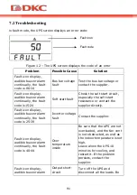
Page 40: ...7 1 7 2 7 1 0 1 2 3 4 Bus 5 6 7 8 9 Bus 10 11 12 13 14 Bus 15 16 17 18 19 Bus 20 21 22 23 24 25 26 27 28 29 30 31 32 33 34 35 36 37 38 39 Bus 40 41 42 43 44 45 46 47 48 49 OP 50 51 52 53 54 55 56 57 5...

Page 41: ...39 60 61 62 63 64 65 66 67 68 69 AC 70 71 72 73 74 75 76 77 78 79 80 81 82 83 84 85 86 87 88 89 AC SCR 90 91 92 93 94 CAN 12 LCD 1 Line bAT 4 4 2 bAT 4 4 bAT bAT 3 byPASS 2...

Page 42: ...40 4 byPASS bat 0 4 4 Line bat 0 4 4 Line byPASS bat 6 5 Line 2 2 FAULT bAT 2 2 FAULT 6 byPASS 2 2 7 2 8 FAULT 13...

Page 43: ...41 10 0 1 2 3 4 5 6 7 8 9 A B...

Page 44: ...42 C D E F 0 1 2 3 4 5 6 7 8 9 A B C D E F EEPROM Median 0 1 2 3 4 5 6 7 8 9 A B...

Page 45: ...43 C D E F 4 0 1 2 3 4 5 6 7 14 2000 7 2 11 00 14...

Page 46: ...44 15 24 25 39 40 44 10 45 49 50 54 55 59 NTC 60 64...

Page 47: ...45 65 69 On 2 3 15...

Page 48: ...6 8 8 1 Small Tower 1000 2000 3000 900 1800 2700 208 220 230 240 50 60 110 276 50 100 176 280 280 300 50 40 70 0 99 THDi 6 25 15 200 220 230 240 1 50 60 0 1 0 9 THDu 2 5 105 120 1 125 150 30 150 300 0...

Page 49: ...47 3 1 90 91 92 85 86 87 ECO 95 96 97 AGM VRLA 24 36 48 72 72 96 1 6 USB RJ45 SNMP 16 8 2 Small Tower 12 SMALLT1A5...

Page 50: ...48 13 SMALLT1A10 14 SMALLT2A5...

Page 51: ...49 15 SMALLT2A10 16 SMALLT3A5...

Page 52: ...50 17 SMALLT3A10...

Page 53: ...214 13 SMALLT2A0 418 191 335 10 5 SMALLT2A5 418 191 335 18 SMALLT2A10 418 191 335 25 8 SMALLT3A0 418 191 335 11 SMALLT3A5 464 191 335 27 2 SMALLT3A10 464 191 335 32 17 8 4 5 C 40 C 25 C 45 C 90 1000...

Page 54: ...52 8 5 004 2011 020 2011 9 2 batt dkc ru service_center...

Page 55: ...53 8 800 250 52 63 service dkc ru www dkc ru...

Page 56: ...54...

Page 57: ...55 English language...

Page 58: ...56...

Page 59: ...UPS 2 Contacts For any information about UPS DKC please contact JSC DKC Russia 125167 Moscow 4 th street of 8 th March 6 bld tel 7 800 250 52 63 For the service issues service dkc ru In case of any t...

Page 60: ...symbols Pay attention to the symbols in the table below Symbol Significations Symbol Significations Caution Protective earth Danger High Voltage Disable mute audible alarm Turn on Overload Turn off Ba...

Page 61: ...low temperature it is necessary to wait before starting up until the device dries both inside and outside 4 If case of any failure please refer to the Troubleshooting section 3 5 Safety regulations an...

Page 62: ...duct range and modifications There are 3 types of the UPSs depending on power 1kVA 2kVA 3kVA All the models have a socket to connect an external battery cabinet to it sold separately The UPSs have dif...

Page 63: ...C Hardware SMALLT3A10S I SI H 8 7 h Charging current 1 Output sockets Schuko IEC Schuko IEC Hardware Table 2 Modifications of the UPS To increase the battery autonomy time a user has to connect an ext...

Page 64: ...autonomy time This configuration guarantees the best service to the User as it supplies clean power uninterruptedly ensuring voltage and frequency stabilization at nominal value Thanks to the double c...

Page 65: ...es that the rectifier does not distort the supply mains with regard to the other loads It also avoids cable overheating due to the harmonics circulation The rectifier is so sized as to supply the inve...

Page 66: ...versa Also the user can independently transfer the UPS to bypass mode by selecting the appropriate mode on the UPS display 4 5 Operating status The UPS has five different operating modes as described...

Page 67: ...e amplitude of the discharging current The voltage drop has no effect on the output voltage which is kept constant by changing the PWM modulation An alarm is activated when the battery is near the min...

Page 68: ...PS 1 Input connection One end of the power cable is connected to the UPS via the IEC C13 C19 connector the input in Figure 6 the opposite end of the power cable is connected to the mains socket 2 Outp...

Page 69: ...end of the cable to the battery pack and then connect the other end to the UPS 3 Before connecting check the polarity of the cables using a specially prepared measuring device Figure 4 External batter...

Page 70: ...rear panel of the UPS it s for SNMP card and dry contacts Users can insert any type intelligent card from those three into it to monitor and manage the UPS And users don t have to turn off the UPS whe...

Page 71: ...S through the web interface and manage it remotely Its main functions are 1 Set all functions by browser 2 Monitor real time status of UPS by browser 3 Support protocols such as TCP IP FTP NTP HTTP SM...

Page 72: ...n PIN1 UPS Failure UPS internal failure O P PIN1short to PIN5 PIN2 UPS Audible Alarm UPS failure Battery low Utility failure O P PIN2 short to PIN5 PIN3 GND I P PIN4 Remote Shutdown I P PIN4 short to...

Page 73: ...g function and remote shutdown function will be approved Monitoring indication showing as below Working state Monitoring results Working normally D8 on Bypass mode D6 on Lose utility D2 on D8 on and D...

Page 74: ...r more than 1 second in battery mode UPS runs the mute function TEST key Press the two keys for more than 1 second in Line mode or ECO mode or CUCF mode UPS runs the self test function SETTING key Not...

Page 75: ...alf a second less than 2 seconds Select the setting option Table 8 Work with UPS 5 2 Display interface Figure 10 Display UPS parameters Display Function Icon display Load icon The approximate load cap...

Page 76: ...uns Fault code will be told in fault mode In setting mode users could adjust different output voltage activate ECO mode activate CUCF mode select an ID number and so on by operating function setting k...

Page 77: ...battery mode 5 3 2 Turn off procedure Turn off the UPS in Line mode Press the OFF key for more than half a second to turn off the UPS After UPS shutdown there is no output If output is needed you can...

Page 78: ...s setup is ON Turn off the UPS in line mode and the bypass setup is ON Overload in line mode Note When UPS is working in bypass mode it has no back up function Line mode In case of input mains corresp...

Page 79: ...g mode automatically LCD displays ECO CUCF mode Frequency conversion mode is mainly to provide a stable voltage and frequency After starting this mode its output will not be affected by utility to mee...

Page 80: ...r for more than half a second less than 2 seconds to inquire parameters The inquired items include Input Battery Output Load and Temperature The displayed items on LCD screen are shown as following LC...

Page 81: ...oltage and frequency of the input As the following graphics shows the input voltage is 220V input frequency is 50Hz Battery Display the voltage and capacity of the battery As the following graphics sh...

Page 82: ...nterface during the operation the letters stop flashing but the numerical values start to flash Press and hold the inquiring key for more than half a second less than 2 seconds select the numerical va...

Page 83: ...isplay Settings CF mode only can be set in STDBY mode You may choose the following two options ON converter mode enable OFF default converter mode disable Output frequency setting LCD display Settings...

Page 84: ...but the voltage output is still four option 240V 230V 220V 208V You can choose to shield the LCD display capacity values whens starting up you can choose whether UPS go directly to the Line mode or by...

Page 85: ...range the UPS operates in battery mode In both cases this is not a fault 2 Check the transition from one mode to another Disconnect power to simulate network failure The UPS transfers into the battery...

Page 86: ...nge of 15 25 C 2 In case of the UPS isn t used for long time it is recommended to fully charge the batteries every 6 months 3 Batteries should not be replaced individually 4 Under normal working condi...

Page 87: ...dle and do not put metal objects on batteries 4 It is strictly forbidden to short circuit the positive and negative terminals of batteries 5 It is strictly prohibited to open the battery due to risk o...

Page 88: ...Over heat yes 45 46 47 48 49 OP inverter short no 50 51 52 53 54 Overload yes 55 56 57 58 59 Line NTC break yes 60 61 62 63 64 Shutdown fault yes 65 66 67 68 69 AC input fuse open yes unused 70 71 72...

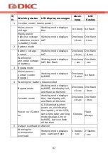
Page 89: ...3 Bypass mode Mains power normal under Bypass Working mode displays byPASS One beep 2 mins No flash 4 Warning for battery disconnected Bypass mode Working mode displays byPASS bat display is 0 and fl...

Page 90: ...beep 2 sec One flash 2sec 7 Fans fault fan icon Fan icon flash working mode displays depending on current mode One beep 2 sec No flash 8 Faults mode Working mode displays FAULT numerical value area di...

Page 91: ...alue Bypass lost Remote Shutdown overload Battery disconnected 0 1 2 3 4 5 6 7 8 9 A B C D E F The second number letter from right to left Display value Overcharging warnings Mains reverse Start up ab...

Page 92: ...fourth number letter from right to left Display value Over load fault Mains lost Bypass abnormal 0 1 2 3 4 5 6 7 Table 14 Display of errors on the screen Example If the alarm code 2000 appears on the...

Page 93: ...plier directly Fault icon display audible buzzer alarm continually the fault code is 25 39 Inverter voltage fault Contact the supplier Fault icon display audible buzzer alarm continually the fault cod...

Page 94: ...inually the fault code is 60 64 Power fault Check whether the input output power are normal or not contact the supplier if it is abnormal Fault icon display audible buzzer alarm continually the fault...

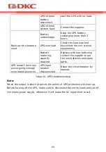
Page 95: ...capacity descend Replace with new batteries contact the supplier to get the new batteries and spare parts UPS doesn t have any power going through even mains power on UPS input breaker disconnected R...

Page 96: ...ng 280 300 derating 50 load Frequency range 40 70 Hz Power factor 0 99 THDi 6 Bypass voltage range 25 15 settable AC output Voltage 200 V 220 V 230 V 240 V 1 settable Frequency 50 Hz 60 Hz 0 1 Hz Powe...

Page 97: ...arging current 1 6 long backup model Communication and control Communication ports USB RJ45 standard Dry contacts SNMP optional Protection Over temp protection Fan testing protection Overload protecti...

Page 98: ...96 8 2 Battery life Runtime graphs of Small Tower series are below Figure 13 Runtime graph of SMALLT1A5 Figure 14 Runtime graph of SMALLT1A10...

Page 99: ...97 Figure 15 Runtime graph of SMALLT2A5 Figure 16 Runtime graph of SMALLT2A10...

Page 100: ...98 Figure 17 Runtime graph of SMALLT3A5 Figure 18 Runtime graph of SMALLT3A10...

Page 101: ...2 Table 17 Dimensions and weight of the UPS 8 4 Environmental conditions Parameter allowable range Operating temperature 0 C 40 C Storage temperature 15 C 45 C Humidity 90 Altitude Below 1000 m withou...

Page 102: ...tional components in the equipment that are not provided by the configuration for example network or other adapters warranty claims are accepted only in case of a defect that is not a direct consequen...

Page 103: ......

Page 104: ......

Reviews: