13
6500-065-K-7-08
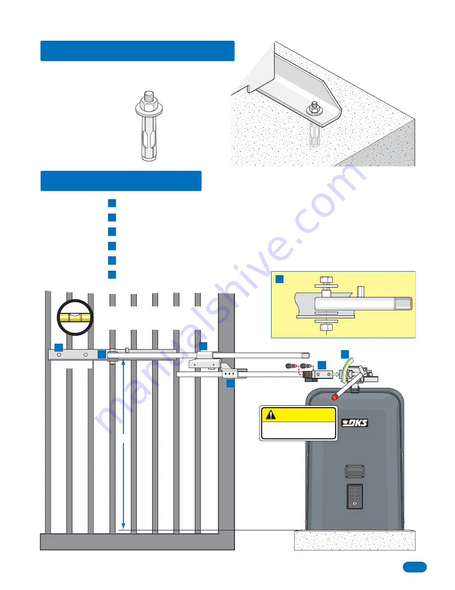
Gate Bracket
Crank Arm
Control Arm
Release hub with release tool.
DO NOT REMOVE HUB!
Bolt crank arm to operator.
Slide elbow assembly on crank arm.
Bolt control arm to gate bracket.
Slide control arm into elbow assembly.
KEEP ARM ASSEMBLY LEVEL
.
Bolt gate bracket to gate.
1.5 Attach Gate Bracket
CAUTION
DO NOT REMOVE HUB!
A
A
D
F
F
E
E
D
B
C
C
B
Gate
Bracket
Control Arm
D
31”
Arm assembly and gate bracket
MUST
be level for gate to function correctly.
Permanently attach the operator to the concrete pad
using four (4) 3/8” x 3” sleeve anchors (not supplied).
1.4 Securing Operator to Pad
Elbow
Assembly
Sleeve Anchor
(Not supplied)
3/8


