background image

 6550-065-A-4-12

31

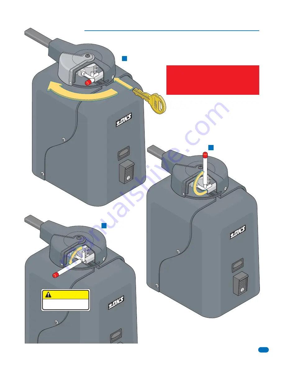
  Be sure that power is removed or shut-off prior to placing the gate operator in manual operation.

Manual Release

Remove release tool and
place where shown.

Release hub.
Gate can now be 
manually operated.

B

C

Unlock the cover and 
rotate sliding door.

A

CAUTION

DO NOT REMOVE HUB!

Never attempt to manually push open 
any gate with an operator attached to 
it until you have verified that power to 
the operator has been shut-off.

Summary of Contents for Series 6550

Page 1: ...TM Copyright 2012 DoorKing Inc All rights reserved Use this manual for circuit board 4405 010 Revision E or higher Date Installed Installer Company Name Phone Number Leave Manual with Owner Heavy Duty...

Page 2: ......

Page 3: ...e Length 25 Ft 25 Ft 25 Ft 25 Ft 25 Ft Cycles Per Hour 60 60 60 60 60 Speed 90 12 14 Sec 12 14 Sec 12 14 Sec 12 14 Sec 12 14 Sec 1 1 1 1 1 Phase Amp 9 7 9 7 4 9 4 9 2 5 Use this manual for the Model 6...

Page 4: ...quirements 1 2 Concrete Pad 1 3 Type of Installations 1 4 Securing Operator to Pad 1 5 Attach Gate Bracket 1 6 Determining Arm Lengths 1 7 Installation of Warning Signs SECTION 2 AC POWER TO OPERATOR...

Page 5: ...ption 5 2 Control Wiring SECTION 7 MAINTENANCE AND TROUBLESHOOTING 32 7 1 Maintenance 7 2 Troubleshooting 7 3 Built in Diagnostics 7 4 Accessory Items 7 5 Gearbox Shaft Extension Replacement Model 655...

Page 6: ...ss opening shall be designed to promote pedestrian usage Locate the gate such that persons will not come in contact with the vehicular gate during the entire path of travel of the vehicular gate The g...

Page 7: ...and maintained serious injuries or death can result Be sure that the installer has instructed you on the proper operation of the gate and gate operator system Be sure that the installer has trained y...

Page 8: ...in which unauthorized access is prevented via supervision by security personnel This table illustrates the entrapment protection requirements for each of the four UL 325 classes A Inherent entrapment...

Page 9: ...or vehicular traffic flow at entrances or exits to areas such as parking garages lots or toll areas VEHICULAR HORIZONTAL SLIDE GATE OPERATOR OR SYSTEM A vehicular gate operator or system that controls...

Page 10: ...ate ref UL325 56 8 4 b Not Allowed OK Closed Gates Gates shall have smooth bottom edges with vertical bottom edged protrusions not exceeding 0 50 inches ASTM F2200 4 3 Opened Gate Opened Gate If dista...

Page 11: ...vides a hold open command to the operator s only if the gate s are at the full open position Separate Pedestrian Walkway Located so pedestrians cannot come in contact with the vehicular gate Warning S...

Page 12: ...e installed in accordance with local codes Never run low voltage rated wire insulation in the same conduit as high voltage rated wire insulation Elbow NO Sweep YES Control and or P A M S Wires Low Vol...

Page 13: ...tes up to 25 feet opening 90 Concrete Pad 90 90 Alternate Installation Concrete Pad Location Concrete Pad Location Operator Installation Recommended for gates up to 18 feet opening 90 Concrete Pad 1 2...

Page 14: ...ncrete Pad 34 14 12 26 30 29 5 24 36 12 2 26 Recommended for gates up to 14 feet opening 90 Permanently attach the operator to the concrete pad using six 6 3 8 x 3 sleeve anchors not supplied 1 4 Secu...

Page 15: ...lease hub with release tool DO NOT REMOVE HUB Bolt crank arm to operator Slide elbow assembly on crank arm Bolt control arm to gate bracket Slide control arm into elbow assembly KEEP ARM ASSEMBLY LEVE...

Page 16: ...recommend that you check with your local building department prior to installing any permanent wiring to be sure that all wiring to the operator both high and low voltage complies with local code requ...

Page 17: ...insulation in the same conduit as high voltage rated wire insulation 100 395 1550 9 7 4 9 2 5 115 208 230 460 162 630 2480 270 1055 4140 405 1580 6210 6550 1 HP 6550 1 HP 6550 1 HP Chassis Ground Neu...

Page 18: ...shown Different lengths sold separately High voltage power and low voltage communications are supplied to the secondary operator by DoorKing s UL approved cable that is run in a single conduit Two co...

Page 19: ...SE SHADOW Loop Terminals SHADOW Output Terminal Self Test Auto Close Timer How LEDs Function DIP Switches Adjust reversing sensitivity for the open AND close direction of the PRIMARY single and SECOND...

Page 20: ...dual gates are used Normal Setting Relay activates when gate is at open limit Shadow loop setting when used Relay activates when gate is not closed Relay activates when gate is opening and open Relay...

Page 21: ...Not use the ON setting for the 6550 operator Switch 6 Sets up the circuit board for a single gate operator or primary secondary dual gate operators Switches 7 8 These work in conjunction with each ot...

Page 22: ...4 15 16 17 18 19 20 2 3 4 5 6 7 8 4405 010 Note If P2 plug is not connected to the circuit board and AC power is turned on alarm will sound and operator will NOT function Operator Opens Counter clockw...

Page 23: ...roperly adjusted BEFORE adjusting the reverse sensors The ideal adjustment will allow the operator to move the gate through its entire travel cycle without reversing but will reverse upon contact with...

Page 24: ...t weight gates may require additional turns of wire through the secondary current sensor while heavier gates may require less turns CAUTION HIGH VOLTAGE Be sure power is turned OFF before changing the...

Page 25: ...ment protection devices than are shown here Install them where necessary to protect against ANY potential entrapment or hazard area OPEN Entrapment Sensor CLOSE Entrapment Sensor Not Used Not Used Low...

Page 26: ...5 6 7 8 9 13 12 11 10 14 15 16 17 18 19 20 20 19 18 17 16 15 14 13 12 11 10 9 8 7 6 5 4 3 2 1 4405 010 Photo Sensor Power Note Photo sensors can be powered by the built in convenience outlets located...

Page 27: ...Loop Detector 9409 LOOP 1 LOOP 2 LOOP 1 To help protect the operator from accidentally closing on vehicles in the gate s path DoorKing highly recommends that loops and loop detectors be installed Loo...

Page 28: ...lly Closed NC operation Contact rating is 1 amp maximum at 24 volts DC NO NC SW 1 1 ON 2 3 4 5 6 7 8 24 volt DC magnetic lock power is provided constantly except when the gate is opening or open Norma...

Page 29: ...rd will activate the gate operator Refer to the manual 2351 065 for detailed information Power is limited to 250 mamps SW 1 Switch 3 Must be ON Power 24 Volt DC and logic output Power is shut off 5 se...

Page 30: ...just and retest the gate operator properly can increase the risk of injury or death 5 Use the emergency release only when the gate is not moving and power has been shut off 6 KEEP GATES PROPERLY MAINT...

Page 31: ...is sensed by the inherent system the gate will reverse and run back to the closed position The time clock input is still present but the gate will not re open Example 2 If the gate is closing and an...

Page 32: ...hardware 1 During normal powered operation emergency vehicles access the gate by use of the Emergency Vehicle Access Device installed on your gate system The type of device that is used in your commun...

Page 33: ...ual Release Remove release tool and place where shown Release hub Gate can now be manually operated B C Unlock the cover and rotate sliding door A CAUTION DO NOT REMOVE HUB Never attempt to manually p...

Page 34: ...and service of this gate operator by a qualified technician should be performed anytime a malfunction is observed or suspected High cycle usage may require more frequent service checks Operator Compon...

Page 35: ...onnect the keying devices one at a time until the LED goes OFF 2 Check any external secondary entrapment protection devices Any short or malfunction in these devices can cause the gate operator to sto...

Page 36: ...rection Turn power OFF and then back ON Activate a keying device Operator should run in the open direction If operator runs in the close direction turn power OFF and change direction switch SW 1 switc...

Page 37: ...ing gates for counter balance P N 1203 084 Hinges Heavy duty ball bearing hinges provide easy swing gate operation P N 1200 009 P N 1200 019 P N 1200 039 Surge Devices High and low voltage surge suppr...

Page 38: ...the TWO allen screws on bottom of hub to remove the complete hub assembly Limit Sensor Assemblies Loosen set screws on plastic limit assemblies to remove them Be CAREFUL not to damage limit sensor wir...

Page 39: ...16 17 18 19 20 2 3 4 5 6 7 8 Model 6550 1 HP 115 VAC Magnetic Open Sensor Reset AC Power Alarm Secondary Interface Terminal Remote Terminal 115 VAC NEU HOT Purple Gray Yellow Orange Red Red Black Red...

Page 40: ...nal Remote Terminal 208 230 460 VAC NEU NEU HOT HOT HOT Purple Gray Yellow Orange Red Red Black Orange Yellow Yellow Orange Orange Brown White Yellow Red Power Power Neutral Brown Blue Brown Blue Whit...

Page 41: ...6550 065 A 4 12 39 Model 6550 1 HP Secondary Operator Magnetic Open Sensor Red Blue Red Orange Orange Yellow Yellow White White Gray Blue Magnetic Close Sensor 1 HP Single Phase...

Page 42: ...nc 120 Glasgow Avenue Inglewood California 90301 U S A Phone 310 645 0023 Fax 310 641 1586 Series 6550 Series 6550 Series 6550 Use this manual for circuit board 4405 010 Revision E or higher Installat...

Reviews: