LMP-100
PROFIBUS/MODBUS GATEWAY
LMP-100 User Manual
MAN-EN-DE-LMP100-01.00_14
Page 25 of 40
All rights reserved to DLG Automação Industrial © 2011 – 2014
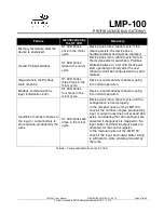
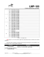
Parameter
Description
Profibus input
Diagnostic data is transferred to the start of the Profibus
input buffer. Thus, the Profibus master accesses diagnostic
data in the same way that it accesses Modbus input data.
The Modbus input data produced by the Modbus rules are
placed right after the diagnostic data.
Profibus extended
diagnostics
Diagnostic data is transferred to the Profibus master via a
Profibus protocol functionality named extended diagnostics.
No diagnostics
(available starting at firmware
version 02.01.00)
None of the previous mechanisms is used. Thus, there is no
way the user can get diagnostic data.
The LMP-100 provides exactly the same diagnostic data for both mechanisms.
The choice of mechanism for accessing diagnostic data must take into account certain
factors. The “Profibus input” option lets diagnostic data to be accessed easily, since they are
mapped to the Profibus input buffer. However, as they are mapped to the the input buffer, they
take space in the buffer, reducing the number of Modbus input variables that can be mapped
through the rules. The “Profibus extended diagnostics” option does not make use of the input
buffer to send diagnostic data, taking advantage of the Profibus extended diagnostics
functionality. Thus, the entire input buffer can be used to access Modbus input variables.
However, the Profibus master configuration required to access the extended diagnostic data is
usually more difficult than the configuration to access data from the input buffer. In addition,
some Profibus masters simply do not allow the user to access extended diagnostics.
Looking at the factors mentioned above, the decision on which diagnostics mechanism to
be chosen is weighted by the effort required to access the data, the possibility of reserving part
of the input buffer for diagnostic data, and also by the extended diagnostic data access in the
chosen Profibus master.
The ST (Status) LED is lit when at least one diagnostic condition is alarmed. When all
conditions return to normal, the ST LED turns off. Even if the user chooses not to access
diagnostic data, through the “No diagnostics” option, the ST LED keeps indicating diagnostic
conditions.
In addition to diagnostic conditions, the ST LED is also used to indicate device failure.
Failures cause the device to stop operating. In such cases, the device automatically reboots
every 10 seconds in an attempt to recover. The failure is identified by the frequency with which
the ST LED flashes. While in failure conditions, the ST LED alternates between a minor cycle in
which it blinks rapidly and large cycle when it is turned off. The number of times the LED blinks
in the minor cycle indicates the specific failure. The RUN LED turns off while the device is in
failure conditions. The table below shows the possible failures, how to identify them and the
possible recovery options.
Summary of Contents for LMP-100
Page 1: ...User Manual Profibus Modbus Gateway MAN EN DE LMP100 01 00_14 Profibus Modbus Gateway LMP 100 ...
Page 2: ......
Page 37: ...Notes ...
Page 38: ......
Page 39: ......


