LMP-100
PROFIBUS/MODBUS GATEWAY
LMP-100 User Manual
MAN-EN-DE-LMP100-01.00_14
Page 33 of 40
All rights reserved to DLG Automação Industrial © 2011 – 2014
Power Supply
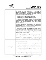
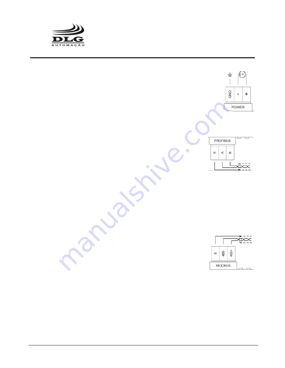
The LMP-100 must be powered through the + e – terminals with voltage in
the range from 20.4 to 28.8 Vdc. The GND terminal is used to ground the “mass”
to the panel. It is recommended to use 1,5mm² cables to the + and – terminals
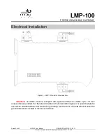
and 2,5mm² cables to the ground. The wiring diagram is described in the picture.
Profibus DP Communications
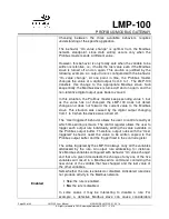
The LMP-100 provides a Profibus DP over RS-485 serial
communication channel. Connections to this channel are made through
terminals named positive (B), negative (A) and shield (S).
Connection to the Profibus DP channel can also be made through
the DB9 connector available on the LMP-100. The connection must be made using standard
Profibus DP connectors.
The DB9 connector and the terminals are internally wired, and can be used together. For
example, the LMP-100 may be connected to the Profibus master through the terminals and a
network analyzer can be simultaneously connected to the DB9 connector, without disturbing the
device operation.
Modbus RTU Communications
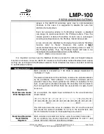
The LMP-100 provides a Modbus RTU over RS-485 serial
communication channel. Connections to this channel are made through
terminals named positive (485+), negative (485-) and shield (S).
Summary of Contents for LMP-100
Page 1: ...User Manual Profibus Modbus Gateway MAN EN DE LMP100 01 00_14 Profibus Modbus Gateway LMP 100 ...
Page 2: ......
Page 37: ...Notes ...
Page 38: ......
Page 39: ......

