Mounting
60
Manual
DLoG X Series
7.3.
Mechanical dynamic loading
Since the DLoG X device is a weighted structure, it is invariable that the unit will be
subject to mechanical dynamic effects. Therefore optimizing the mounting can be very
helpful. Please refer to
Appendix C: Mechanical dynamic loading.
7.4.
Power supply
An integrated, electrically isolated AC or DC power supply is available for all devices of
the DLoG X-series.
The power adaptor is designed to fulfill the requirements for the full range of operating
temperatures. In addition, you can operate additional modules and/or external devices.
7.4.1.
DC power packs
DLoG X devices are available with various integrated DC power supply units.
DLoG X 7:
•
DC power pack with 12/24 VDC input voltage, maximum output 30 W
•
DC power pack with 24/48 VDC input voltage, maximum output 30 W
DLoG X 10 and X 12:
•
DC power pack with 24/48 VDC input voltage, maximum output 100 W
•
DC power pack with 24/48 VDC input voltage, maximum output 60 W
•
DC power pack with 12 VDC input voltage, maximum output 100 W
DLoG X devices must only be connected to a SELV
6)
(Safety Extra
Low Voltage) circuit. Ensure that there is a suitable disconnecting
device such as a power switch or circuit breaker in the power
supply circuit. Ensure that the disconnecting device isolates all
supply voltage lines. Furthermore, the DC+ connecting cables must
be protected by a fuse (16 AT max). The ignition connecting cables
must be protected by a fuse of the following type: 5x20 mm T
125 mA L / 250 V, for example, a Wickmann 195-125 mA / 250 V.
Summary of Contents for DLoG X 10
Page 1: ...3 10 DLoG X 7 DLoG X 10 DLoG X 12 Manual ...
Page 3: ......
Page 12: ......
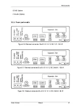
Page 55: ...Initial operation DLoG X Series Manual 43 COM2 Options 13 Audio Option ...
Page 87: ...Boot loader DLoG X Series Manual 75 Figure 9 2 Boot loader diagram 2 ...
Page 109: ...Audio Option DLoG X Series Manual 97 Figure 13 2 Audio port circuit diagram ...


