


4
Assembly
Hi-Cap 40 Grain Cleaner
Step 27 Install the belt shield by putting a ½” nut on each shield mounting bolt, then place
a ½” flat washer to each bolt and continue by putting the shield into position. Se-
cure with another ½” flat washer, followed by a ½” nut. Adjust the shield so that it
will properly protect both pulleys. See Photo 43.
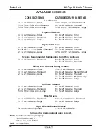
Step 28 The cone screens are usually installed at the factory. Should replacement or
change be necessary, remove the straps and self-tapping screws. A variety of
cone screens are available for the individual needs. See Page ???.
Outside screens are installed by wrapping the screen around the outside of the
drum. BE SURE outside screen is lapped as shown in Photo 46. If incorrectly
installed, grain will get behind the screens, causing them to work their way off the
drum. Place head of machine screws in direction of drum rotation.
For easy placement of outside drum screens, two door springs can be attached to
either a small piece of steel or wood with hooks to hook into the screen. Then, by
using a stick or broom handle, tap the screen lightly. The door springs will take all
the excess slack out of the outside screen so the drum straps can be easily put on
and secured. Straps should be secured with ¼” and 2-
1
/
2
” machine screws and
nuts. See Photos 47 and 48.
NOTE
Screen lap and outside drum straps should NOT be spliced on the same tumbling
bar.
Outside drum straps that are placed directly over drum rings should be tightened
securely. Common sense should be used when tightening straps that only come
in contact with the outside drum tumbling bars. Deforming of the bars could result
if these straps are over-tightened. BE SURE straps are positioned as shown in
Photos 47 and 48. REMEMBER, screen lap and outside drum straps should NOT
be on the same tumbling bar.
Step 29 By loosening the setscrews and turning the turnbuckle, you can adjust the slant of
your drum for proper operation. See Photo 49. The grain will pass through the
screener faster with a steep slant. The cleaning action will be more thorough with
less slant.
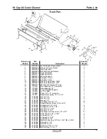
IF TRASH PAN EQUIPPED:
Step 30 The drum side panel will mount with the channel edge on the top and to the out-
side. Bolt the end shield to the front end of the side panel using two ¼” x ½” pan
head machine screws, hex flange lock nuts.
Step 31 Bolt the two posts to the drum side panel using ¼” x ¾” hex bolts, lock washers
and hex nuts.
Assembly Instructions
(continued)
Summary of Contents for HI-CAP 40
Page 1: ...OWNER S MANUAL HI CAP 40 GRAIN CLEANER PNEG 1146 Date 9 21 06 PNEG 1146...
Page 2: ......
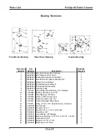
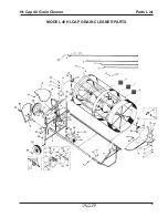
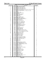
Page 15: ...9 Parts List Hi Cap 40 Grain Cleaner MODEL 40 HI CAP GRAIN CLEANER PARTS...
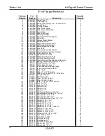
Page 17: ...11 Parts List Hi Cap 40 Grain Cleaner 8 x 8 Auger...
Page 19: ...13 Parts List Hi Cap 40 Grain Cleaner 4 x 15 Fines Auger...
Page 20: ...14 Parts List Hi Cap 40 Grain Cleaner...
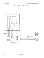
Page 22: ...16 Parts List Hi Cap 40 Grain Cleaner Wiring Diagram 115V or 230 V...


