


7
Assembly
Hi-Cap 40 Grain Cleaner
Assembly Instructions
(continued)
Step 18 Put the flat end of the guide rods into the bushings provided at the back of the
hopper. Align the holes in the rod with those in the bushing and secure with
1
/
8
” x
1-
1
/
4
” cotter pins as shown in Photos 32 and 33.
Step 19 Place the slide flow restrictor adjustment handle through the bushing welded to
the 2” strap brackets and bolt to the flow restrictor tube with one 5/16” x ¾” hex
head bolt and lock washer. Finish by turning the wing bolt into the nut welded on
bushing of the strap bracket. See Photos 34, 35 and 36.
Step 20 Install the hopper latch and upper glide rod support bracket by placing the ends of
the glide rod support bracket through the holes in the hopper and to the pointed
guide rod ends. Fasten the latch to the hopper with the two 3/8” flat washers, and
two cotter pins. See Photos 37 and 38.
Step 21 Assemble the hopper extensions using six ¼” x ½” pan head machine screws and
¼” hex head flanged whiz lock nuts. Once the upper extensions are assembled,
fasten the glide rod guides to the upper extensions using ten ¼” x ½” pan head
machine screws. See Photos 39 and 40. BE SURE to install bolts as shown in
Photo ???.
Step 22 Slide hopper extension assembly onto glide rods. Lift up latch and finish assem-
bly by placing hairpin clips through holes of guide rods. See Photos 41 and 42.
OPERATE Auger and OBSERVE for proper rotation.
Change wires in motor for rotation correction.
Summary of Contents for HI-CAP 40
Page 1: ...OWNER S MANUAL HI CAP 40 GRAIN CLEANER PNEG 1146 Date 9 21 06 PNEG 1146...
Page 2: ......
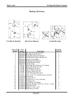
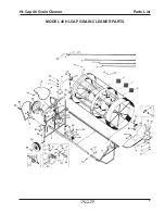
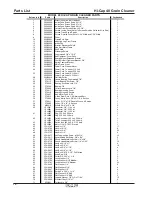
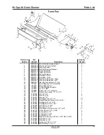
Page 15: ...9 Parts List Hi Cap 40 Grain Cleaner MODEL 40 HI CAP GRAIN CLEANER PARTS...
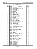
Page 17: ...11 Parts List Hi Cap 40 Grain Cleaner 8 x 8 Auger...
Page 19: ...13 Parts List Hi Cap 40 Grain Cleaner 4 x 15 Fines Auger...
Page 20: ...14 Parts List Hi Cap 40 Grain Cleaner...
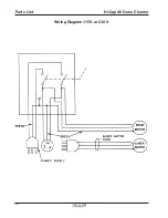
Page 22: ...16 Parts List Hi Cap 40 Grain Cleaner Wiring Diagram 115V or 230 V...


