1
Assembly
Hi-Cap 40 Grain Cleaner
Assembly Instructions
Step1
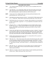
The component parts necessary for the make-up of the completed scanner are
shown in Photo 1.
Step 2
Use eight 3/8” x 1” hex head bolts, bolt the side rails to the front and rear frame
ends. Secure with 3/8” lock washers and nuts, as shown in Photos 2, 3 and 4.
Before tightening bolts, square the side rails with front frame end.
NOTE
If trash pan is to be installed, attach the two side panel frame brackets when
attaching side rails. See Photo 5 and 6.
Step 3
Put wheels to the axles as shown in Photo 7. Secure with ¾” SAE washers and 3/
16” x 1” cotter keys. Place wheel on axle with the grease zerk on the outer side.
Step 4
Mount switch box to front frame end. To attach, open switch box cover and bolt to
switch mounting plate, using three ¼” x ¾” pan head bolts, lock washers and nuts.
See Photo 8.
Step 5
Using two 3/8” x 1-
1
/
2
” bolts; bolt dual bearing on the front frame-bearing mount.
See Photos 9 and 10. Fasten each bolt with 5/16” flat washer, 3/8” lock washer
and nut. BE SURE the dual bearing is positioned as shown in Photo 10 with
indentation up.
Step 6
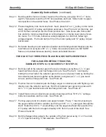
Put the 3/8” pivot bolts into the drum belt tightener as shown in Photo 11. Next, put
the pivot bolts through the lower half of the double bearing and the bearing plate;
fasten with 5/16” flat washer, 3/8” lock washer and nut. Slide dual bearing to the
top of the slotted holes and TIGHTEN TEMPORARILY. See Photos 11, 12 and 13.
Step 7
Put the tension spring bracket on the 3/8” x 5-
1
/
2
” bolt, with the 3/8” nut, and turn
into bearing plate as shown in Photo 14.
Step 8
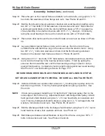
Place the 7/8” x 7-3/8” shaft, (keyway both ends) into double bearing with an equal
amount of shaft protruding from each end of dual bearing. See Photo 15. Next,
put a locking collar on each end of shaft and lock. Tighten setscrews. Last, place
½” moon keys into shaft. See Photos 16 and 17. Lock locking collar in direction of
rotation.
Step 9
Place the 7/8” x 2-
1
/
2
” two-groove “A” section pulley on the 7/8” shaft as shown in
Photo 18. Position pulley so that it is flush with the outside end of the shaft.
Tighten setscrews firmly.
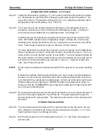
Step 10 Slide the 14” pulley onto the 7/8” shaft, hub first. Position it tightly against bearing
locking collar. Tighten setscrews firmly. See Photo 19.
Summary of Contents for HI-CAP 40
Page 1: ...OWNER S MANUAL HI CAP 40 GRAIN CLEANER PNEG 1146 Date 9 21 06 PNEG 1146...
Page 2: ......
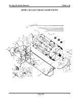
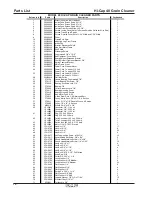
Page 15: ...9 Parts List Hi Cap 40 Grain Cleaner MODEL 40 HI CAP GRAIN CLEANER PARTS...
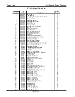
Page 17: ...11 Parts List Hi Cap 40 Grain Cleaner 8 x 8 Auger...
Page 19: ...13 Parts List Hi Cap 40 Grain Cleaner 4 x 15 Fines Auger...
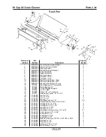
Page 20: ...14 Parts List Hi Cap 40 Grain Cleaner...
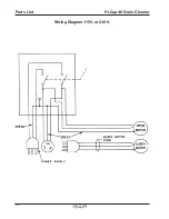
Page 22: ...16 Parts List Hi Cap 40 Grain Cleaner Wiring Diagram 115V or 230 V...


