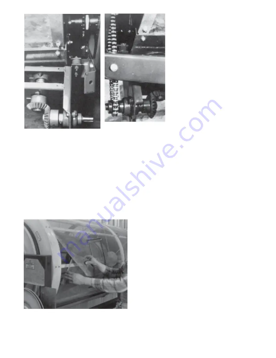
Photo 61
Photo 62
Step 65.
Apply a thin line of
grease to the 3/4”
gear drive shaft,
and slide the shaft
into the five (5)
inch auger tube
end until the 1/4”
holes line up with
the set screw hole
in the bearing.
Screw the 1/4” x
1-1/4” set of
screws through
the bearing collar,
tube and shaft
until it seats
against the other
side of the bearing
collar. Only about
1/16” of the set
screw should be
exposed. Tighten
both set screws in
the bearing collar.
Step 66.
Install the #40
drive chain. Align
the sprockets and
tighten the idler.
See Photos 61 &
62.
Attach the drive cover with the #10 x 3/4” self-tapping screws.
NOTE:
LOWER FRAME BRACE REMOVED FOR
PHOTOGRAPHIC PURPOSES.
Photo 63
Step 67.
Install two front panel extensions
(left and right) beside front switch
box, using six 1/4” x 5/8” hex
flange screws and 1/4” lock
washers and hex nuts.
Step 68.
INSTALLATION OF OUTSIDE
DRUM SCREENS: There are
three sections of outside screens
provided, along with one screen
tool. Simply take the screen that
is the same width as the section of
drum you intend to screen, wrap
the screen around the drum, and
be sure to lap the screen as
shown in Photo 63, or see
Drawing on Page 19.
18
Summary of Contents for Hi Cap 54
Page 1: ...OWNER S MANUAL Hi Cap 54 Grain Cleaner PNEG 1147 PNEG 1147 Date 3 1 02...
Page 43: ...MODEL 54 HI CAP DRUM 34...
Page 45: ...36...
Page 46: ...37...
Page 47: ...38...
Page 48: ...39...
Page 53: ...44...
Page 55: ...46...
Page 57: ...48...
Page 58: ...49...


