Step 71.
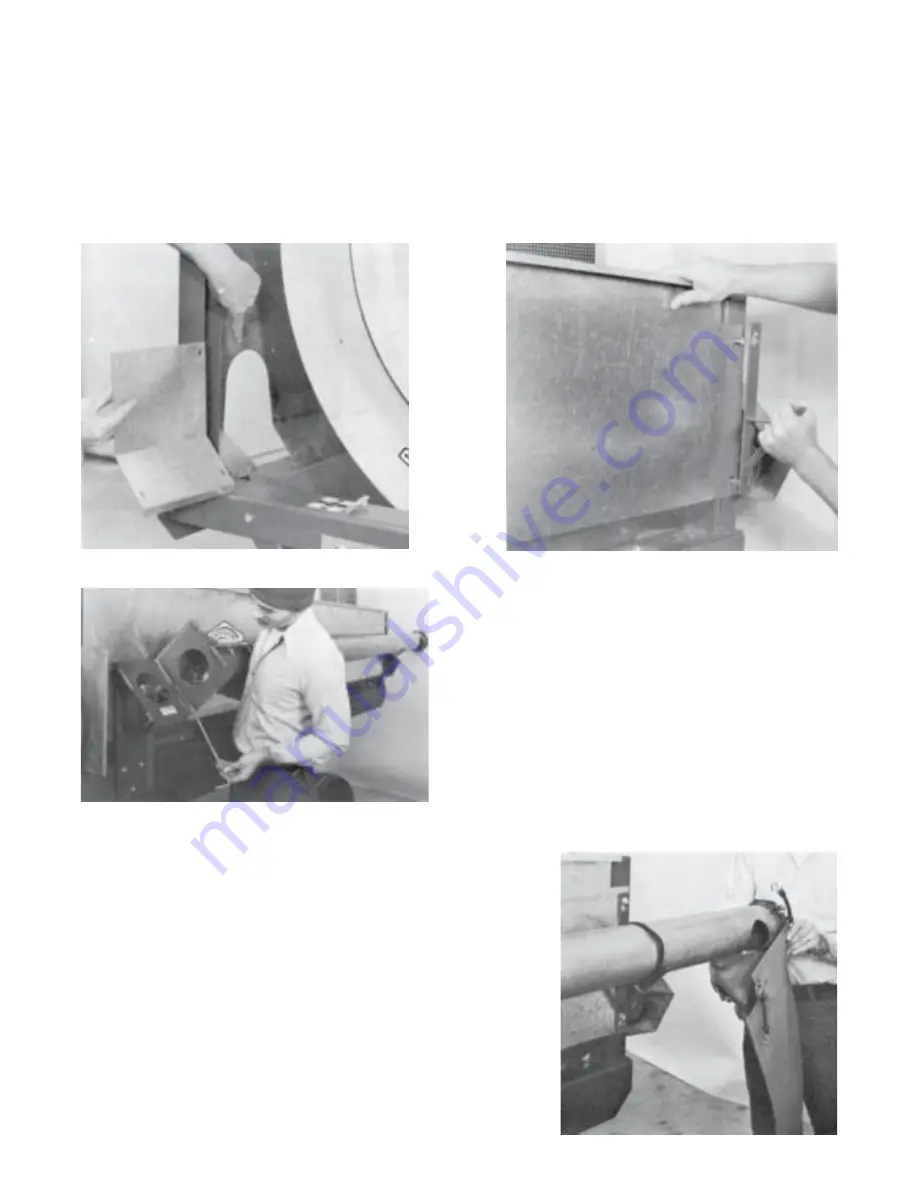
Mount the drum side panels. Before securing, determine which panel will go
on the side opposite 5” trash auger. Bolt the cover over the opening on the
inside of the side panel, using four 1/4” x 5/8” hex flange screws and hex
flange lock nuts. See Photo 66. Continue by bolting side panels to cleaner
frame, using four 5/16” x 3/4” hex flange screws on each side. Before
tightening the two rear flange screws on the side of the 5” auger, mount the
rear 5” auger carrier by inserting heads of bolts through the slots of the carrier
bracket. Push bracket down and finish by securely tightening all the side
panel bolts. See Photo 67.
Photo 66
Photo 67
Step 72.
Lay discharge end of 5” auger
into auger carrier. Align hinge
and insert hinge pin from lower
side. Secure with hair pin cotter.
To put 5” auger in operational
position, tip auger up and insert
second hinge pin and hair pin
cotter. See Photo 68.
WHEN LIFTING 5” TRASH AUGER INTO OPERATING
POSITION, A SCREWDRIVER MAY BE NEEDED TO
ASSIST IN ALIGNING THE TWO SECTIONS OF AUGER.
ROTATION ON ONE SECTION MAY BE REQUIRED
SHOULD DRIVE PINS COINCIDE.
Step 73.
Fasten vinyl drop chute to 5” auger, using
two 4” rubber tie straps. See Photo 69.
With 5” auger in transport position, BE SURE RUBBER
STRAP IS USED TO HOLD AUGER IN CARRIER.
Photo 68
Photo 69
20
Summary of Contents for Hi Cap 54
Page 1: ...OWNER S MANUAL Hi Cap 54 Grain Cleaner PNEG 1147 PNEG 1147 Date 3 1 02...
Page 43: ...MODEL 54 HI CAP DRUM 34...
Page 45: ...36...
Page 46: ...37...
Page 47: ...38...
Page 48: ...39...
Page 53: ...44...
Page 55: ...46...
Page 57: ...48...
Page 58: ...49...


