SuperSigma2 AM PMS
–
V1.5.6 17-1-2020
Page 44 (97)
©2019 DMC GmbH Herten Germany
M1-8P
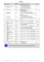
Speed 4 demand ”Pspeed4”
This sets the pump speed when the switch wired to pin 4 of 35-way Connector is active.
When pump speed 4 is active and the pump potentiometer, Speed 2 and Speed 3 are not active, it will override all other
speed requests, except for the power steer trigger input (pin 6 of 35-wy connector). When the power steer trigger input
is active, the current speed demand will be the higher between Speed 4 and Speed 6. The pump motor will accelerate or
decelerate to the new speed demand using the programmed Acceleration and Deceleration rates.
M1-9P
Sp
eed 5 demand ”Pspeed5”
This sets the pump speed when the switch wired to pin 5 of 35-way Connector is active.
When pump speed 5 is active and the pump potentiometer, Speed 2, Speed 3 and Speed 4 are not active, it will set the
speed requests, except for the case in which the power steer trigger input (pin 6 of 35-wy connector) is active. When the
power steer trigger input is active, the current speed demand will be the higher between Speed 5 and Speed 6. The pump
motor will accelerate or decelerate to the new speed demand using the programmed Acceleration and Deceleration rates.
M1-10P
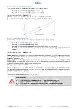
Speed 6 demand (power steer) ”Pspeed6”
This sets the pump speed when the switch wired to pin 6 of 35-way Connector is active.
When both the power steer trigger input and another speed input are active, the resultant speed demand will be the
higher between the two. The pump motor will accelerate or decelerate to the speed demand from input 6 using the rates
defined by parameter “
Acceleration delay for speed 6 demand (pwrStr) ”Paccel6””
.
M1-11P
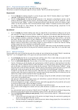
Minimum motor speed in cutback conditions ”MinSpeed”
If some performance limitation is active (Low voltage, I2T, Performance Table, Motor Overtemperature, Controller
Overtemperature, Undervoltage) and it is limiting the speed below this value, the motor is stopped and a failure is signaled
(F26). This is necessary to protect pump from spinning too slow.
M1-12P
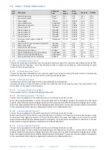
Acceleration delay for speed 6 demand (pwrStr) ”Paccel6”
When the power steer trigger is active and its demand is prevailing, the controller uses this rate for acceleration and
deceleration instead of those set by
and
.
M1-13P
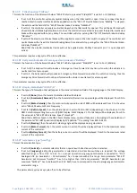
Power steer delay ”PStrDly”
This sets the period that the Power Steer speed 6 will remain active after the trigger source input, pin 6 on 35-Way
Connector, has been deactivated.
M1-14P
Accelerato
r pot minimum ”AccMin”
This sets the voltage on the Potentiometer input that will correspond to zero speed.
M1-15P
Accelerator pot maximum ”AccMax”
This sets the voltage on the Potentiometer input that will correspond to maximum speed.
This setting is used in conjunction with parameter
Maximum pot speed 1 ”Potmax1””.
M1-16P
Speed threshold to enter in end of braking mode ”SpdThEbM”
See setting
Speed threshold to enter end of braking mode ”SpdThEbM””
for traction control.
M1-17P
Ramp time from SpdThSpC to zero ”SpdRmpTm”
See setting
Speed threshold Ramp time to zero speed ”SpdRmpTm””
for traction control.
M1-18P
Zero Speed threshold to end braking “ZSpdTh”
See setting
Zero Speed Threshold to enter hill hold or neutral brake end ”ZSpdTh”” for traction control.

