DMEGC Photovoltaic Modules Installation Manual
- 7 -
module to the support rails with bolts. The frame of each module has 4 mounting holes, ideally placed to
optimize the load handling capability, to secure the modules to supporting structure.
To maximize mounting longevity, DMEGC strongly recommends the use of corrosion proof (stainless
steel) attachment hardware. The tightening torque (suggest stainless steel M8 bolts) should be around 15-20
N
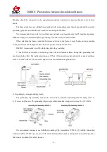
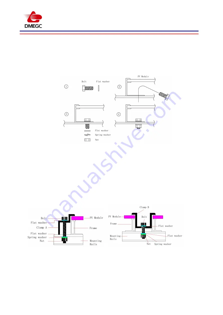
m, the mounting details are shown in the following figures:
2. Mounting with Clamps
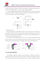
When choosing this type of clamp-mounting method, use at least four clamps on each module, two
clamps should be attached on each long sides of the module (for portrait orientation) or each short sides of
the module (for landscape orientation). Depending on local wind and snow loads, additional clamps may be
required to ensure that modules can bear the load.
The clamp must overlap the module frame by at least 7mm but no more than 10mm.Modules clamps
should not come into contact with the front glass and must not deform the frame. Be sure to avoid
shadowing effects from the module clamps. The mounting details are shown in the following figures.
4.5 Attachment guidelines
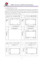
The Standard/lower loading capacity applies to normal environment : the modules are tested under a
maximum positive pressure of 2400 Pa, and negative pressure of 2400 Pa, the modules are designed to
meet a maximum positive pressure of 1600Pa, and negative pressure of 1600 Pa, this design load was then

