DMEGC AC Module Installation Manual
- 14 -
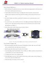
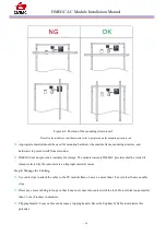
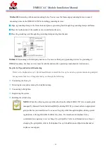
Figure 4-8. Position of the mounting structure rail
Please fix the module so that the microinverter is not placed on the mounting structure rail.
Appropriate material should be used for mounting hardware (the module frame, mounting structure, and
hardware) to prevent itself from corrosion.
DMEGC does not provide a warranty for clamps. The module warranty DMEGC provides shall be voided if
clamps selected by the customer are an improper material or size.
Step 8: Manage the Cabling
Use cable clips to attach the cable to the PV module frame. Leave no more than 1.8 m (six feet) between cable
clips.
Dress any excess cabling in loops so that it does not come into contact with the roof. Do not form loops smaller
than 12 cm (4 inches) in diameter.
Tripping Hazard. Loose cables can become a tripping hazard. Dress the Enphase Q Cable to minimize this
potential.


