DMEGC AC Module Installation Manual
- 18 -
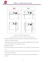
cable fixing holes or to the mounting structure. Also, if the cable is not secured, a force may be applied to the
cable from the outside, and the module may be damaged.
Do not insert PV cable between back side and mounting structure
rail. Note that when snow or wind load is
applied to the module, increased load may be applied to the cable.
Verify that all fittings are properly installed to protect cables against damage and prevent moisture intrusion.
Check your local codes for requirements.
Step 15: Ground the DMEGC ACMs
Choose to use grounding clamps or module mounting holes to ground the modules. Or, you can use a reliable
third-party grounding system.
All methods:
A. Ground the module frames to protect the array from lightning and static-electricity damage using Method A, B,
or C.
B. Be sure that the grounding device will fully contact the inner side of the aluminum alloy and penetrate the
frame surface oxide film.
C. Make a connection from the grounding conductor to earth using a suitable earth ground electrode.
WARNING:
Risk of equipment damage. Do not drill additional grounding holes on module frame.
The module frame has been drilled and marked for grounding. Use the grounding holes only for
grounding, and do not used them for mounting or other purposes.
NOTE:
The grounding conductor or strap can be copper, copper alloy, or any other material acceptable
for use as an electrical conductor per the National Electrical Codes. The grounding wire material and
size must meet all local and regional requirements.
Method A:
Grounding with grounding clamps.
Locate the grounding hole (diameter Ø4 mm) at the edge of the module frame back.
Use 12 AWG copper core wire for the grounding clamp, and do not damaged the copper wire during installation.
Torque to 2.3 N. m.


