DMEGC Solar PV Modules Installation Manual
•
Do not place connectors in locations where water could
easily accumulate.
5.2 Grounding
•
Although the modules are certified to Safety Class II, we
recommend them to be grounded and that module
installation should comply with all applicable local
electrical codes and regulations. Minimum size of
equipment grounding conductors for ground raceway and
equipment should be considered. Grounding connections
should be installed by a qualified electrician. Connect
module frames together using adequate grounding cables:
the use of 4-14 mm² (AWG 6-12) copper wire is
recommended. Holes provided for this purpose are
identified with a grounding symbol
(IEC 61730-1).
All conductive connection junctions must be firmly fixed.
•
Do not drill any extra ground holes for convenience as this
will void the modules warranty.
•
All bolts, nuts, flat washers, lock washers and other
relevant hardware should be made of stainless steel,
unless otherwise specified.
•
DMEGC Solar does not provide grounding hardware.
•
The grounding method described below is commended
by DMEGC Solar.
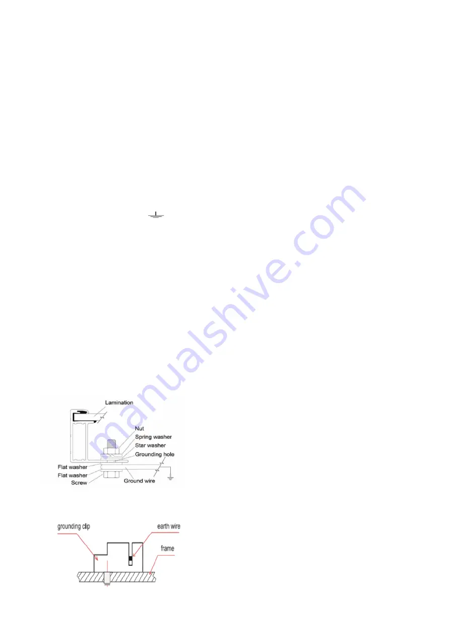
Grounding by grounding bolt
•
Use M8 bolt and washers to bond the ground wire and
aluminum frame through the grounding holes (as shown
figure 1
). The tightening torque is 3-7N.m. All nuts and
washers should be made of stainless steel.
figure 1
Grounding by using grounding clamp
figure 2
•
As shown in the
figure2
, the grounding clip assembly
consists of a slider, base, and self
–
captivating thread
–
cutting screw or 8
–
32 screw and hex nut. The grounding
clip accepts solid uninsulated copper wire sizes 10 or 12
AWG.
Addition Third-party Grounding Devices
•
DMEGC Solar
’s
Modules can be grounded using third
party grounding devices so long as they are certified for
grounding modules and the devices are installed
according to the manufacturer’s specified instructions.
6.
Mounting Instructions
The applicable regulations pertaining to work safety, accident
prevention and securing the construction site must be
observed. Workers and third party personnel shall wear or
install fall arrest equipment. Any third party need to be
protected against injuries and damages.
•
The mounting design must be certified by a registered
professional engineer. The mounting design and
procedures must comply with all applicable local codes
and requirements from all relevant authorities.
•
The module is considered to be in compliance with IEC
61730 and IEC 61215 only when the module is mounted
in the manner specified by the mounting instructions
included in this installation manual.
•
The system designer and installer are responsible for load
calculations and for proper design of support structure.
•
Any module without a frame (laminate) shall not be
considered to comply with the requirements of IEC 61730
unless the module is mounted with hardware that has
been tested and evaluated with the module under this
standard or by a field Inspection certifying that the
installed module complies with the requirements of IEC
61730.
•
DMEGC Solar does not provide mounting hardware.
•
Standard modules can be mounted onto a support
structure using one of several approved methods as
described below. For information about other installation
methods, please contact your local representative.
Failure to use a recognized installation method will void
the DMEGC Solar
’s
warranty.
•
Use appropriate corrosion-proof fastening materials. All
mounting hardware (bolts, spring washers, flat washers,
nuts) should be hot dip galvanized or stainless steel.


