DIVERSIFIED METAL FABRICATORS, INC.
ROTO 180
2-2
© 2017 DMF, Inc. All Rights Reserved.
2.1
OPERATIONS – HYDRAFORCE MANIFOLD
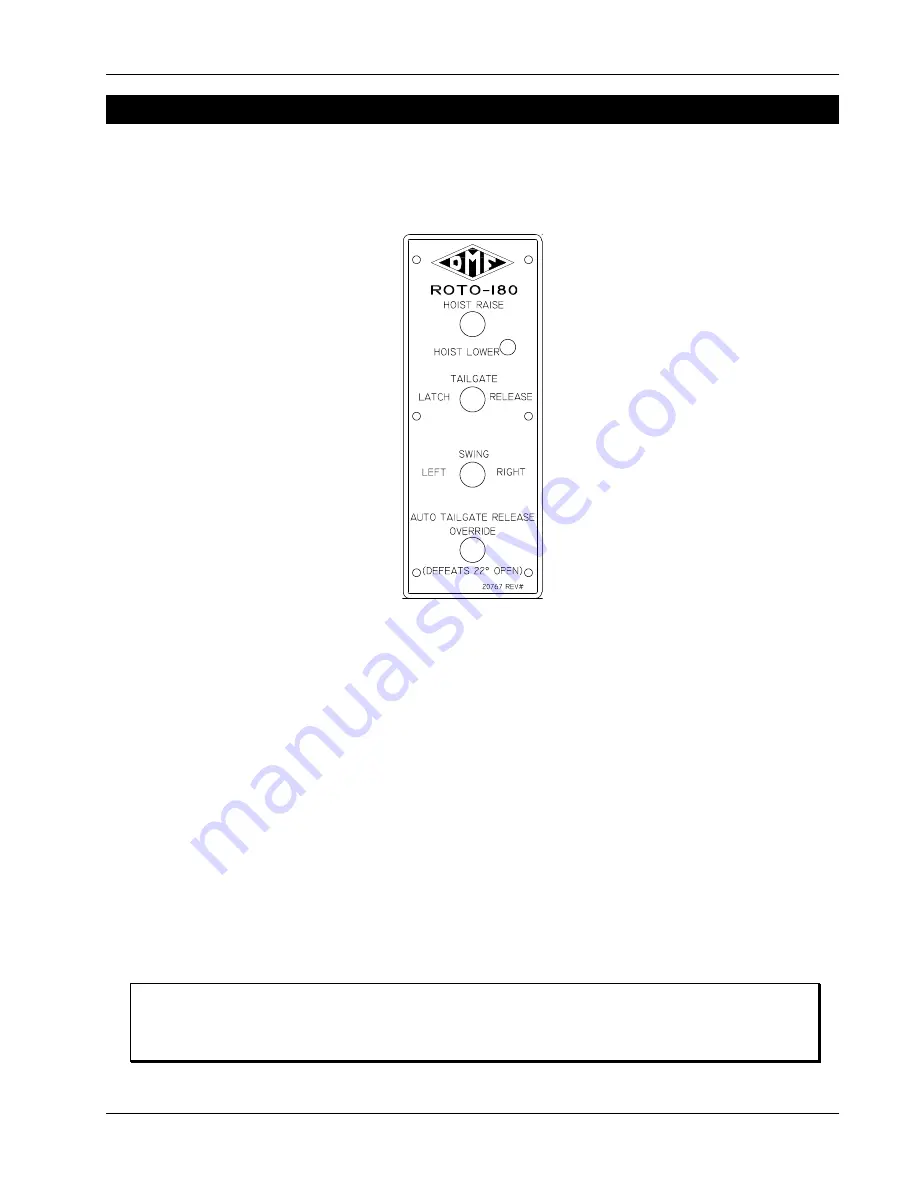
The HydraForce manifold is located within the ROTO 180 system subframe. The manifold is
controlled from a set of toggle switches mounted to the dashboard of the truck, see Figure 2.1.
If equipped, a vibrator toggle switch may be included on this mount and a tarp control switch
mounted to the dashboard.
Figure 2.1 - HydraForce Manifold Dashboard Mounted Controls
2.1.1
Enable System
1.
Engage the PTO as outlined in the PTO Operations Manual provided with the truck.
2.
If the truck is equipped with a hydraulic selector valve, shift it to activate the ROTO 180
system.
3.
PULL out or toggle the “SYSTEM ENABLE” switch, to enable the system. The red light will
come on to indicate that the system is operational.
2.1.2
Disable System
1.
PUSH in or toggle the switch, to disable the system. The red light will turn off to indicate
the end of the task.
2.
Disengage the PTO as outlined in the PTO Operations Manual provided with the truck.
2.1.3
Raising Body – HydraForce Manifold
NOTE
Operation of the ROTO 180 system with the body turned away from the center position
requires the use of either manual or hydraulic Raildogs to stabilize the truck. For
operation of Raildogs, refer to the separate “Raildog” manual.
Summary of Contents for ROTO-180
Page 28: ......
Page 44: ......
Page 49: ......
Page 51: ......
Page 55: ......
Page 58: ......
Page 63: ......
Page 64: ......
Page 73: ......
Page 74: ......
Page 75: ......
Page 76: ......
Page 77: ......
Page 78: ......
Page 79: ......
Page 80: ......
Page 81: ......
Page 82: ......
Page 83: ......
Page 84: ......
Page 88: ......
Page 89: ......
Page 90: ......
Page 91: ......
Page 93: ......
Page 94: ......
Page 95: ......
Page 96: ......
Page 97: ......
Page 98: ......
Page 99: ......
Page 100: ......
Page 101: ......


