background image

®  

2007


1.1 Safety instructions 


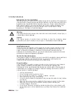
Information for Your Own Safety


              This manual does not contain all of the safety measures for operation of the equipment 

(module, device), because special operating conditions, and local code requirements or 
regulations may necessitate further measures. However, it does contain information 

which must be read for your personal safety and to avoid material damages. This 
information is highlighted by a warning triangle and is represented as follows, 

depending on the degree of potential danger. 


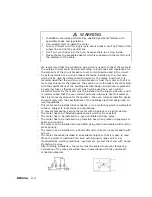
Warning 

This means that failure to observe the instruction can result in death, serious injury or 
considerable material damage. 
 

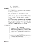
    Caution 

This  means hazard of electric shock and failure to take the necessary safety 

precautions will result in death, serious injury or considerable material damage. 


Qualified personnel 

Commissioning and operation of the equipment (module, device) described in this 
manual may only be performed by qualified personnel. Qualified personnel in the  
sense of the safety information contained in this manual are persons who are 

authorized to commission, start up, ground and label devices, systems and circuits 
according to safety and Regulatory standards. 


Use for the intended purpose 

The equipment (device, module) may only be used for the application cases specified in 
the catalogue and the user manual and only in connection with devices and 

components recommended and approved by DMMetering. 
 

Proper handling 

The prerequisites for perfect, reliable operation of the product are proper transport, 

proper storage, installation and assembly, as well as proper operation and 
maintenance. When operating electrical equipment, certain  parts of this equipment 

automatically carry dangerous voltages. Improper handling can therefore result in 
serious injuries or material damage. 


?


Use only isolated tools. 

?


Do not connect while circuit is live (hot). 

?


Do not connect the meter to a 3 phase - 400VAC – network. 

?


Place the meter only in dry surroundings. 

?


Do not mount the meter in an explosive area or expose the meter to dust, mildew 

and insects.   

?


Make sure the used wires are suitable for the maximum current of this meter. 

?


Make sure the AC wires are connected correctly before activating the 
current /voltage to the meter. 

?


Do not touch the meter connecting clamps directly with your bare hands, with 
metal, blank wire or other material as you will have the chance of an electrical 

shock. 


Summary of Contents for PRO-75 SERIES

Page 1: ...se two wire energy meter 1 1 Safety instruction 1 2 Foreword 1 3 Performance criteria 1 4 Specifications 1 5 Basic errors 1 6 Description 1 7 Dimensions 1 8 Installation 1 9 Operating 1 10 Troubleshoo...

Page 2: ...up ground and label devices systems and circuits according to safety and Regulatory standards Use for the intended purpose The equipment device module may only be used for the application cases speci...

Page 3: ...mark of Inepro Industries Ltd member of the Inepro Group The other names appearing in this manual may be trade names the use of these names by third parties for their own purposes may infringe the rig...

Page 4: ...tage withstand 2KV for 1 minute Impulse voltage withstand 6KV 1 2 S waveform Basic current Ib 10A Maximum rated current Imax 100A Operational current range 0 4 Ib Imax Over current withstand 30Imax fo...

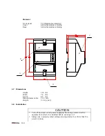
Page 5: ...ns Height 130 mm Width 76 mm Depth 65 mm Max diameter cable 11 5 mm Weight 0 2 Kg net 1 8 Installation CAUTION Turn off and lock out all power supplying the energy meter and the equipment to which it...

Page 6: ...codes and regulations To prevent tampering secure the meter with a padlock or a similar device The meter has to be installed against a wall which is fire resistant The meter has to be installed in a g...

Page 7: ...proportion to the measured energy for accuracy testing The pulse output is a polarity dependant passive transistor output requiring an external voltage source for correct operation For this external...

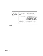
Page 8: ...ct Maybe there is a fault in the inside circuit Check switch or circuit breaker and fuse or thermal cut off Re install terminal screws on the L1 and L2 N Make sure all screws are fixed Than there shou...

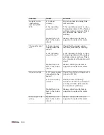
Page 9: ...e circuit Check that the power supply indicator RED LED is burning If the operating power is too low the spacing interval of the pulses will take some more time This is why it seems like the meter won...

Page 10: ...lease contact DMMetering dealer in your in your region Your local DMMetering distributor Email support dmmetering com www dmmetering com Inepro Industries Ltd Room 2303 Office Tower 1 Harbour Road Wan...

Reviews: