SCS-105 SDLC SINGLE LINE
SERVICE RECEIVER
Installation Guide
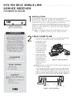
Figure 1: SCS-105 SDLC
Single Line Service Receiver
DESCRIPTION
CABLE CONNECTIONS
1. Connect the 4-wire phone cable from the appropriate phone
jack into the TELCO port on the rear of the SCS-105.
2. Connect the 4-wire
data cable to the
rear HOST port on
the SCS-105 receiver.
3. Connect the 25-pin
male connector to
the convertor cable
using the 25-pin
female connector.
4. Connect the 9-pin
male connector on
the convertor cable
to the serial port
on the back of the
computer. Refer to
Figure 2 for cable
connectors.
Note:
If you do not wish for the SCS-105 to pickup incoming calls,
call DMP Technical Support
The serial port selected must be free from any other devices
such as modems, mouse, or printers. You cannot use COM 1 if
you are using COM 3 for another device. Also, you cannot use
COM 2 if you are using COM 4 for another device. These COM
ports have the same interrupt and cannot be used together.
TELCO TELEPHONE
Incoming
Phoneline
To Optional
Telephone
12 VDC
HOST
AC/DC
Power Converter
RS-232 to Remote Link,
System Link, or Host Computer
Figure 3: Rear Connections
The SCS-105 Single Line Service
Receiver provides a control interface
between a host computer and one
or more DMP panels. The SCS-105
allows users with DMP Remote
Link™ or System Link™ software
to remotely program and perform
control functions on control panels
without using a DMP SCS-1R Security
Control Receiver. The SCS-105 comes
preset for standard 2-wire digital
dialer operation and can easily be
configured to work with 2-wire or
4-wire multiplex systems.
Compatibility
•
All DMP panels
What’s Included
•
Converter Cable
•
4-Wire Connector
•
376 Power Supply
Questions?
Contact DMP tech Support by phone
(between 7 AM and 7 PM Central Time)
or by email:
•
1-888-4DMPTEC (1-888-436-7832)
•
417-831-9362
•
techsupport@dmp.com
1
2
4-Wire Connector to
HOST Port on SCS-105
25-Pin
Female
Connector
Convertor
Cable
9-Pin
Female
Connector
25-Pin
Male
Connector
Figure 2: Cable Connectors
INSTALLATION
The best place to install the SCS-105 is near your Remote Link™
or System Link™ computer. This allows you to monitor the
communication status LEDs while receiving or sending transmissions,
and provides easy access to the line monitor volume control.
If you are using the SCS-105 with DMP Remote Link or System Link
software, you must make a few configuration adjustments before you
contact any subscriber accounts. See section 3 for more information
about configuring.
Note:
For additional information, see the Remote Link User’s
Guide (LT-0565) or System Link User’s Guide (LT-0570).
MODEL SCS-105
Single Line
Service Receiver
RESET
VOLUME
LT OL CD RD TD ST


