Digital Monitoring Products
XR150INT/XR550INT Series Installation Guide
6
INSTALLATION
Installation
4.1 Mounting the Enclosure
The metal enclosure for the XR150INT/XR550INT Series panels must be mounted in a secure, dry place to
protect the panel from damage due to tampering or the elements. It is not necessary to remove the panel
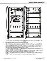
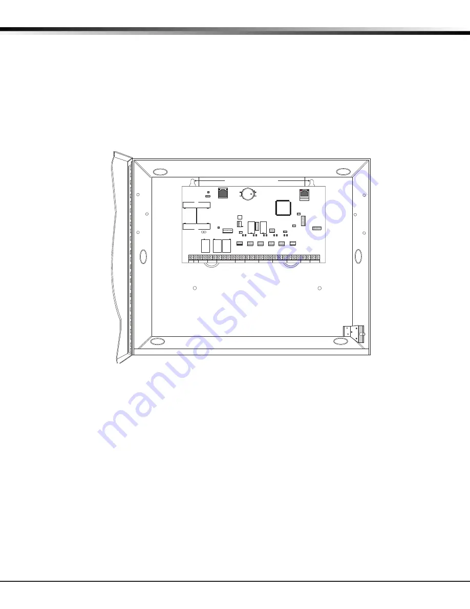
PCB when installing the enclosure. Figure 2 shows the mounting hole locations for the Model 350INT/350AINT
Enclosures. Figure 3 shows the Model 352PINT panel cabinet and 352S shelf cabinet for multiple batteries.
The 350AINT Attack Resistant enclosure is factory shipped with one knockout on the top left of the
enclosure. As needed, additional knockouts or antenna exits may be added at the time of installation. See
Figure 2 for the positions on the enclosure that can be added. Each additional knockout must be filled with
conduit.
Enclosure Mounting Holes
3-Hole
Pattern for
Accessory
Modules
Tamper Switch
for 350A Attack
Resistant
Enclosure
Dual 1 3/4" and 1 3/8" Conduit Knockouts
Battery Shelf holds up to three 7 Ah Batteries
XR550INT Panel
1
AC
2
AC
3
B+
4
B-
5
BELL
6
GND
7
RED
8
YEL
9
GRN
10
BLK
11
SMK
12
GND
13
Z1
14
GND
15
Z2
16
Z3
17
GND
18
G4
19
Z5
20
GND
21
Z6
22
Z7
23
GND
24
Z8
25
Z9+
26
Z9-
27
Z10+
28
Z10-
PROG
RED
BLK
J8
LX500
RED
BLK
LX600
RED
BLK
J14
J9
J15
LX7
00
RED
BLK
LX800
RED
BLK
J15
LX900
RED
BLK
XMIT
XBUS
RCV
LX
XMIT
RCV
700
600
XMIT RCV
XBUS
J13
Output 2
XMIT
RCV
500
PROG
XMIT RCV
J8
PROG
K7
OVC
OUTPUTS
LEV
J2
OUT2
OUT1
Output 1
K6
LOAD
J16
J7
RESET
J16
EXP
CELL
MODULE
J24
E
THERNE
T
J1
BATT START
PWR
50 VA
75 VA
J12
PHONE LINE
J3
BT1
3V
BR2325
* 350A Optional Knockout
*
*
*
*
*
J6
K
893A
or 277
3
4
5
6
Figure 2: XR550 International Series panel in Model 350 or 350A Enclosure

