background image

Digital Monitoring Products


XR150INT/XR550INT Series Installation Guide

10

INSTALLATION

6.6  Battery Supervision

The XR150INT/XR550INT Series panels tests the battery when AC power is present. The test is done every 

three minutes and lasts for five seconds. During the test, the panel places a load on the battery; if the 

battery voltage falls below 11.2 VDC a low battery is detected. If AC power is not present, a low battery is 

detected any time the battery voltage falls below 11.2 VDC.
If a low battery is detected with AC power present, the test repeats every two minutes until the battery 

charges above 12.6 VDC indicating the battery has restored voltage. If a weak battery is replaced with a 

fully charged battery, the restored battery will not be detected until the next two minute test is completed.

6.7  Battery Cutoff

The panel disconnects the battery any time the battery voltage drops below 10.2 VDC. This prevents battery 

deep discharge damage.

6.8  Power Requirements

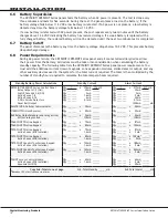
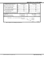
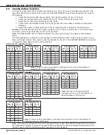
During AC power failure, the XR150INT/XR550INT Series panel and all connected auxiliary devices draw 

their power from the battery. All devices must be taken into consideration when calculating the battery 

standby capacity. The following table lists the XR150INT/XR550INT Series panel power requirements. You 

must add the additional current draw of keypads, zone expansion modules, smoke detector output, and any 

other auxiliary devices used in the system for the total current required. The total is then multiplied by the 

number of standby hours required to calculate the total ampere-hours required.

Standby Battery Power Calculations

Standby Current

Alarm Current

XR150INT/XR550INT Series Control Panel 

Relay Outputs 1-2 (ON) 

Switch Grounds 3-6 (ON) 

Active Zones 1-8 

Active Zones 9-10 

2-Wire Smoke Detectors 

Panel Bell Output

Qty      1      

Qty _______

Qty _______

Qty _______

Qty _______

Qty _______

x 174mA

30mA

5mA

1.6mA

4mA

0.1mA

  174 mA

______

______

______

______

______

Qty      1     

Qty _______

Qty _______

Qty _______

Qty _______

Qty _______

x

217mA

30mA

5mA

2mA*

30mA

0.1mA

1500mA

  217 mA

______

______

______

______

______

______mA

263LTE-INT-A Cellular Communicator

Qty _______

x

20mA ______

Qty _______ x

20mA ______

1100XINT Wireless Receiver

Qty _______

x

25mA ______

Qty _______ x

35mA ______

860 Relay Output Module (one relay active) 

All four relays active

Qty _______

x

34mA

138mA

______

______

Qty _______  x

34mA

138mA

______

______

7060-WINT Thinline Keypad

Qty _______

x

72mA ______

Qty _______ x

87mA ______

7063-WINT Thinline Keypad

Qty _______

x

85mA ______

Qty _______ x

100mA ______

7070-WINT Thinline Keypad 

Active Zones (EOL Installed)

Qty _______

x

72mA

1.6mA

______

______

Qty _______

Qty _______

x

x

87mA

2mA*

______

______

7073-WINT Thinline Keypad 

Active Zones (EOL Installed)

Qty _______

x

85mA

1.6mA

______

______

Qty _______

Qty _______

x

x

100mA*

2mA

______

______

7872-WINT Graphic Touchscreen Keypad 

Active Zones (EOL Installed)

Qty _______

x 130mA

1.6mA

______

______

Qty _______

Qty _______

x

x

188mA

2mA*

______

______

7873-WINT Graphic Touchscreen Keypad 

Active Zones (EOL Installed)

Qty _______

x 143mA

1.6mA

______

______

Qty _______

Qty _______

x

x

243mA

2mA*

______

______

734INT Access Control Module 

Active Zones (EOL Installed) 

Annunciator (ON)

Qty _______

Qty _______

x

x

40mA

1.6mA

______

______

Qty _______

Qty _______

Qty _______

x

x

x

60mA

2mA*

20mA

______

______

______

Copy Sub-Totals to next page


Sub-Total Standby ______mA                     Sub-Total Alarm ______mA     

*

Based on 10% of active zones in alarm.

Summary of Contents for XR150 series

Page 1: ...INSTALLATION GUIDE XR150 XR550 INTERNATIONAL SERIES CONTROL PANEL...

Page 2: ...ries Installation Guide MODEL XR150 XR550 INTERNATIONAL SERIES PANELS INSTALLATION GUIDE 2021 Digital Monitoring Products Inc Information furnished by DMP is believed to be accurate and reliable This...

Page 3: ...ing Keypads and Zone Expansion Modules 7 4 3 Connecting LX Bus AX Bus and Keypad Bus Devices 8 4 4 Wireless Keypad Association 8 5 1 AC Terminals 1 and 2 9 5 2 50VA 75VA 3 Pin Header for Transformer T...

Page 4: ...13 2 Model 300 Harness Wiring 16 13 3 Model 860 Relay Module 16 Wireless Bus Expansion 14 1 Description 16 14 2 Wireless Bus LEDs 16 LX BusTM AX BusTM Expansion 15 1 LX Bus HeadersLX Bus AX Bus Heade...

Page 5: ...9 and 10 1 4 Keypad Bus You can connect up to a total of 16 of the following supervised keypads and expansion modules to keypad bus Alphanumeric keypads One four eight and sixteen zone expansion modul...

Page 6: ...2 2 Zone Expansion Each panel provides multiple options for zone expansion 10 on board zones Up to 64 programmable keypad zones Up to 500 LX Bus zones Using DMP LCD keypad remote zone capability and...

Page 7: ...age to the equipment or improper operation of one or more components in the system See the example shown below Always ground the panel before applying power to any devices The panel must be properly g...

Page 8: ...h 16 gauge wire 70 feet with 18 gauge wire 40 feet RED BLACK Cold Water Pipe Earth Ground Bell 3 3k Ohm Resistor DMP Model 309 3 3k Ohm Resistor DMP Model 309 s Supervised Circuit Zone 9 Zone 10 22 ga...

Page 9: ...tor for external contact Provides Disarm Disable functionality 1122INT PIR Motion Detector Provides motion detection with pet immunity 1128INT Wireless Glassbreak Detector Provides fully supervised lo...

Page 10: ...e positions on the enclosure that can be added Each additional knockout must be filled with conduit Enclosure Mounting Holes 3 Hole Pattern for Accessory Modules Tamper Switch for 350A Attack Resistan...

Page 11: ...re mounting the base connect the keypad wire harness leads to the keypad cable from the panel and to any device wiring run to that location Then attach the harness to the pin connector on the PC board...

Page 12: ...wire distance from the panel increases DC voltage on the wire decreases Maximum number of LX Bus AX Bus devices on the first 2 500 foot circuit is 40 devices 4 Maximum voltage drop between the panel...

Page 13: ...or Model 369 12 VDC 7 Ah sealed lead acid rechargeable battery Batteries supplied by DMP have been tested to ensure proper charging with DMP products GEL CELL BATTERIES CANNOT BE USED WITH THE XR150I...

Page 14: ...INT XR550INT Series Control Panel Relay Outputs 1 2 ON Switch Grounds 3 6 ON Active Zones 1 8 Active Zones 9 10 2 Wire Smoke Detectors Panel Bell Output Qty 1 Qty _______ Qty _______ Qty _______ Qty _...

Page 15: ...x 20mA 1 6mA ______ ______ Qty _______ Qty _______ x x 20mA 2mA ______ ______ 716INT Output Expansion Module Active Form C Relays Qty _______ Qty _______ x x 13mA 1 6mA ______ ______ Qty _______ Qty...

Page 16: ...7 Ah Batteries 7 7 Ah Batteries 9 Ah Batteries 18 Ah Batteries Max Ah Available No of Batteries Max Ah Available No of Batteries Max Ah Available No of Batteries Max Ah Available No of Batteries Max...

Page 17: ...mum current in a fire listed application 8 3 Terminal 8 YELLOW Terminal 8 receives data from keypads and zone expansion modules It cannot be used for any other purpose 8 4 Terminal 9 GREEN Terminal 9...

Page 18: ...Zone 1 voltage sensing 19 Zone 5 voltage sensing 14 Ground for Zones 1 and 2 20 Ground for Zones 5 and 6 15 Zone 2 voltage sensing 21 Zone 6 voltage sensing 16 Zone 3 voltage sensing 22 Zone 7 voltag...

Page 19: ...ame zone Caution Performing a Sensor Reset momentarily drops power to the devices on Zones 9 and 10 The panel views these zones 9 and 10 as Open while the power is absent Dry Contact Relay Outputs 12...

Page 20: ...low For listed applications devices connected to the outputs must be located within the same room as the panel Output Color Wire Output Color Wire 3 Red 1 5 Green 3 4 Yellow 2 6 Black 4 13 3 Model 860...

Page 21: ...dress AX500 AX600 AX700 AX800 AX900 Door Zones Door Zones Door Zones Door Zones Door Zones 1 501 501 504 601 601 604 701 701 704 801 801 804 901 901 904 2 505 505 508 605 605 608 705 705 708 805 805 8...

Page 22: ...allation Sheet LT 1316 for complete information PHONE LINE RJ Connector 17 1 Description Connect the panel to the public telephone network by installing a DMP 356 RJ Cable between the panel PHONE LINE...

Page 23: ...or two seconds After resetting the panel begin programming within 30 minutes If you wait longer than 30 minutes you must reset the panel again 18 2 TAMPER Header The TAMPER header is for use with the...

Page 24: ...the standoff hole in the panel PCB 2 Align the PCB standoff with the standoff hole in the module PCB 3 Press the module PCB card 12 pin connector onto the CELL MODULE header on the panel while applyin...

Page 25: ...equirements for interconnections equipment using radio frequency techniques EN 50131 6 2008 Alarm systems Intrusion systems Power supplies EN 50136 1 2012 Alarm systems Alarm transmission systems and...

Page 26: ...1233INT 2021 Digital Monitoring Products Inc 21131 Documentation Security Grade 3 Environmental Class II Power Supply Type A Power Input 18 VAC 50 Hz 400 mA Class II EN 50131 1 Notification Requiremen...

Reviews: