XR150INT/XR550INT Series Installation Guide
Digital Monitoring Products
17
INSTALLATION
LX-Bus
TM
/AX-Bus
TM
Expansion
15.1 LX-Bus HeadersLX-Bus/AX-Bus Headers
XR150INT/XR550INT Series panels are capable of providing zone, output, and access control expansion
by connecting hardware modules to the AX/LX-Bus headers on the control panel. XR150INT panels are
manufactured with one LX-Bus header labeled LX500. AX-Bus operation does not apply to XR150INT panels.
XR550INT panels are manufactured with five AX/LX-Bus headers labeled LX500-LX900. Application determines
if a header works in AX-Bus or LX-Bus operation.
LX-Bus (XR150INT/XR550INT)
There are five LX-Bus headers near the bottom of the
XR150INT/XR550INT panel:
• LX500 provides zones 500-599 (all panels).
• LX600 provides zones 600-699 (XR550INT only).
• LX700 provides zones 700-799 (XR550INT only).
• LX800 provides zones 800-899 (XR550INT only).
• LX900 provides zones 900-999 (XR550INT only).
AX-Bus (XR550INT V111 or higher):
AX-Bus operation is compatible only with XR550INT control
panels and DMP Model 734INT Wiegand Interface door access modules. The 734INT provides one Form-C
relay output and four expansion zones. AX-Bus operation is not compatible with addressable zone and output
expanders. Each AX-Bus represents predetermined addresses for 734INT operation: 16 addresses for 734INT
door relay outputs, and 64 addresses for 734INT expansion zones.
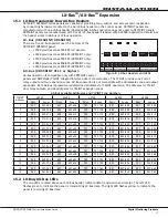
AX-Bus Available Addresses and 734INT Zone Numbers
734INT
Address
AX500
AX600
AX700
AX800
AX900
Door
Zones
Door
Zones
Door
Zones
Door
Zones
Door
Zones
1
501
501-504
601
601-604
701
701-704
801
801-804
901
901-904
2
505
505-508
605
605-608
705
705-708
805
805-808
905
905-908
3
509
509-512
609
609-612
709
709-712
809
809-812
909
909-512
4
513
513-516
613
613-616
713
713-716
813
813-816
913
913-916
5
517
517-520
617
617-620
717
717-720
817
817-820
917
917-920
6
521
521-524
621
621-624
721
721-724
821
821-824
921
921-924
7
525
525-528
625
625-628
725
725-728
825
825-828
925
925-928
8
529
529-532
629
629-632
729
729-732
829
829-832
929
929-932
9
533
533-536
633
633-636
733
733-736
833
833-836
933
933-936
10
537
537-540
637
637-640
737
737-740
837
837-840
937
937-940
11
541
541-544
641
641-644
741
741-744
841
841-844
941
941-944
12
545
545-548
645
645-648
745
745-748
845
845-848
945
945-948
13
549
549-552
649
649-652
749
749-752
849
849-852
949
949-952
14
553
553-556
653
653-656
753
753-756
853
853-856
953
953-956
15
557
557-560
657
657-660
757
757-760
857
857-860
957
957-960
16
561
561-564
661
661-664
761
761-764
861
861-864
961
961-964
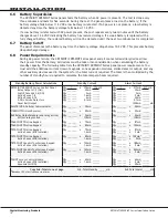
15.2 LX-Bus/AX-Bus LEDs
The two LEDs, located above each LX-Bus header, indicate data transmission and receipt. The left LED
flashes green to indicate the panel is transmitting LX-Bus data. The right LED flashes yellow to indicate the
panel is receiving LX-Bus data.
Figure 8: LX-Bus Headers and LEDs
PROG
LX500
LX600
LX700
LX800
LX900
10
BLK
11
SMK
12
GND
13
Z1
14
GND
15
Z2
16
Z3
17
GND
18
Z4
19
Z5
20
GND
22
Z7
21
Z6
RED
BLK
RED
BLK
RED
BLK
RED
BLK
RED
J17
BLK
XMIT
RC
V
RED
BLK
XMIT
RC
V
J8
J14
J9
XMIT
RCV
XMIT
RCV
XMIT
RCV
XMIT
RCV
PROG
500
600
700


