XR150/XR550 Series Canadian Installation Guide
Digital Monitoring Products
7
INSTALLATION
Installation
4.1
Mounting the Enclosure
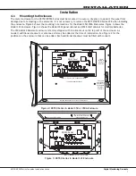
The metal enclosure for the XR150/XR550 Series must be mounted in a secure, dry place to protect the panel from
damage due to tampering or the elements. It is not necessary to remove the XR150/XR550 Series PCB when installing
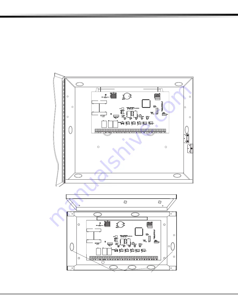
the enclosure. Figure 2 shows the mounting hole locations for the Model 350/350A Enclosures. Figure 3 shows the
Model 341 Enclosure. Figure 4 shows the Model 352X panel cabinet and 352S shelf cabinet for multiple batteries.
The 350A Attack Resistant enclosure is factory shipped with one knockout on the top left of the enclosure. As
needed, additional knockouts or antenna exits may be added at the time of installation. See Figure 2 for the
positions on the enclosure that can be added. Each additional knockout must be filled with conduit.
Enclosure Mounting Holes
3-Hole
Pattern for
Accessory
Modules
Front and
Rear Tamper
Switches for
350A Attack
Resistant
Enclosure
Dual 1 3/4" and 1 3/8" Conduit Knockouts
Battery Shelf holds up to three 7 Ah Batteries
XR550 Panel
* 350A Optional Knockout
*
*
*
*
*
J6
K
J23
Figure 2: XR550 Series in Model 350 or 350A Enclosure
Dual 1/2" and 3/4" Conduit Knockouts
Lid Mounting Holes (4 places)
Lid Mounting Holes
(4 places)
Enclosure Mounting Holes (4 places)
PEMs for optional battery bracket.
See 341 Installation sheet for
additional information.
XR550 Panel
J6
K
J23
Figure 3: XR550 Series in Model 341 Enclosure


