12
MSEV Series and USHX Hardware Installation Manual Rev 1.7
6.
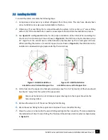
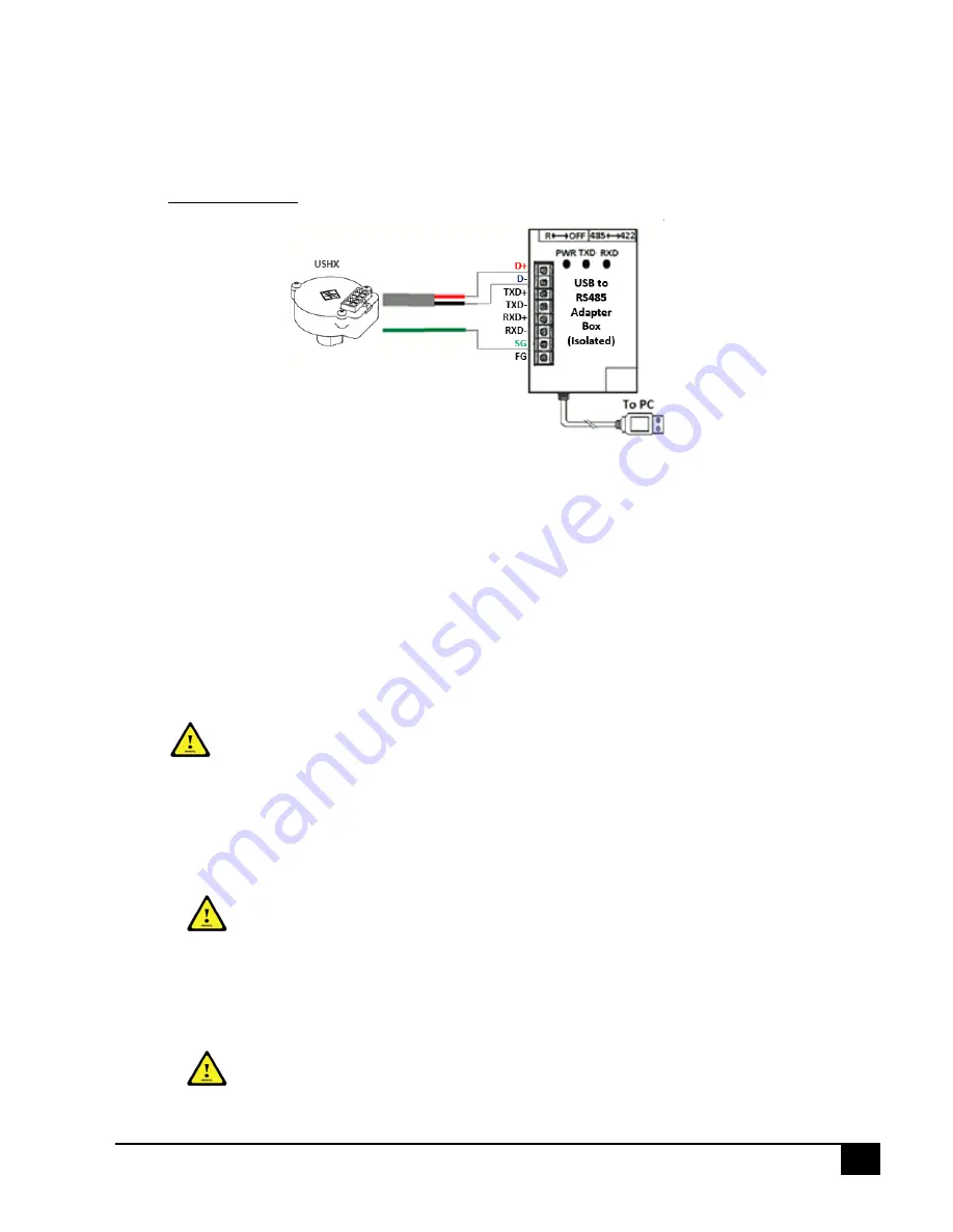
Connect the RS485 communication wires (2-wire gray cord that contains a red and a black wire
and the green data ground wire) to the D+, D-, and SG terminals on the USB-to-RS485 converter
as shown below in Figure 3-3. For the USHX setup, the RS485 will require an adapter with built-in
electrical isolation.
Figure 3-3 USHX-to-RS485 converter connection
7.
Connect the RS485 adapter box to the computer via a USB port.
8.
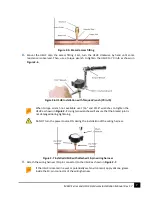
Connect the PWM output wires (two 18 AWG white wires) to the MSEV/HC-MSEV/VHC-MSEV
electrical connections. These wires are non-polar.
9.
The general purpose wires (20 AWG brown/purple wires) must remain unconnected, be
terminated with wire nuts, and wrapped with electrical tape so they do not form short circuits
with each other or any other wires or metal surfaces.
10.
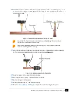
Tape any dangling wires to existing structures such as copper and water lines with at least 4-5
sections of electrical tape each. Use zip ties on top of the electrical tape in a neat and organized
manner to further secure the wires.
Ensure that all cables are distanced from fans, high voltage wires (120-208 VAC), and
potential areas of water. Ensure that any bare cable leads are covered with electrical
tape and do not touch other wire leads or any metal structures.
11.
The electrical wiring for Single USHC and MSEV/HC-MSEV/VHC-MSEV or Single USHS setup is now
complete.
3.2
Multiple USHCs and MSEV Series Valves or Multiple USHSs
Do NOT turn the power source ON until all electrical wiring setup is complete.
1.
Check the voltage type (either 12V or 24V) of the MSEV series valves. It can be found on the MSEV
series valve model number label. The power source required will be based on the MSEV series
valve voltage type.
Ensure that the power source voltage matches the MSEV series valve voltage type. If
a 12V MSEV series valve is powered by a 24V power source, the valve will fail due to


