background image


17


MSEV Series and USHX Hardware Installation Manual Rev 1.7


4   Troubleshooting 

The following section describes troubleshooting procedures for the USHX and MSEV series valve. If 

the system is running abnormally, first check the wiring for broken or shorted connections. Repair broken 
wires  and remove  short circuits  between  touching  wires or  between wires  and any metal  surfaces.  If 
there are no wiring problems, then use the following table to further diagnose the problem (assuming 
everything else in the system such as the compressor, evaporator, filter drier, etc. is working properly
). 

Problem 

Possible Cause 

Action 

High Superheat: 


This may indicate 

that the MSEV 

series valve is not 

fully opening. 

Common symptoms 

include compressor 

short cycling. 


Inadequate Power to 

the Valve 

Check  the  power  source  voltage.  The  voltage  leaving  the 
transformer  and  entering  the  USHX  should  be  close  to  the 
intended  supply  voltage  (24V  or  12V).  If  the  transformer 
voltage is too low, there is a problem with the transformer or 
its  wiring.  If  the  voltage  entering  the  USHX  is  low  and  the 
transformer  voltage  is  normal,  there  is  a  problem  with  the 
terminal connections or interconnecting wiring to the USHX.  

Temperature Sensor 

Incorrectly Mounted 

Check  the  mounting  of  the  USHC  temperature  sensor.  The 
sensor  should  be  firmly  mounted  to  the  outlet  of  the 
evaporator at a 10 o’clock or 2 o’clock position. Check that the 
temperature sensor is wrapped with insulated tape. 

Over Voltage to the 

MSEV Series Valve 

Check the resistance across the valve terminals. Remove both 
power connections from the MSEV series valve and measure its 
resistance with a multimeter. The resistance reading should be 
between 26-34Ω for a 24V valve and between 6-13Ω for a 12V 
valve. If the resistance is significantly out of this range (or zero), 
the MSEV series valve is damaged and should be replaced. 

MSEV Series Valve 

Slow to Open 

Check  that  the  USHX  Gain  settings  meet  the  system 
requirements. (Also applicable if the MSEV series valve opens 
too quickly.)  
Connect and disconnect the power to the valve several times 
to manually actuate the valve.  

Low Superheat: 


This may indicate 

that the MSEV 

series valve is 

staying open. 

Common 

symptoms include 

compressor 

frosting. 

MSEV Series Valve 

Slow to Close 

Check  that  the  USHX  Gain  settings  meet  the  system 
requirements. (Also applicable if the MSEV series valve closes 
too quickly.) 
Connect and disconnect the power to the valve several times 
to manually actuate the valve.  

Temperature Sensor 

Incorrectly Mounted 

Check  the  mounting  of  the  USHC  temperature  sensor.  The 
sensor  should  be  firmly  mounted  to  the  outlet  of  the 
evaporator at a 10 o’clock or 2 o’clock position. Check that the 
temperature sensor is wrapped with insulated tape. 

Severely Oversized 

Valve 

Determine the capacity of the evaporator and check the valve 
model  number  to  confirm  that  the  two  are  compatible 
regarding their capacities. 


Summary of Contents for A12V-C112

Page 1: ...ar Silicon Expansion Valve HC MSEV Very High Capacity Modular Silicon Expansion Valve VHC MSEV Universal SuperHeat Controller Sensor USHX Revision 1 7 DunAn Microstaq Inc 4120 Freidrich Lane Suite 225 Austin Texas 78744 United States 512 628 2890 www dmq us com Published July 2019 2019 ...

Page 2: ...348 A12V C352 A12V C355 A12V C358 A24V C332 A24V C338 A24V C343 A24V C348 A24V C352 A24V C355 A24V C358 This manual is applicable to the following VHC MSEV model numbers A12V C6612 A12V C6650 A12V C6715 A12V C6773 A12V C6799 A24V C6612 A24V C6650 A24V C6715 A24V C6773 A24V C6799 This manual is applicable to the following USHX model numbers USHC G1 3b BAAAXXX USHS G1 3b BAAAXXX Additional Product M...

Page 3: ...yms 1 1 4 About the MSEV Series and the USHX 2 2 Mechanical Installation 4 2 1 Installing a MSEV Series Valve 4 2 2 Installing the USHX 6 3 Electrical Wiring 10 3 1 Single USHC and MSEV Series Valve or Single USHS 10 3 2 Multiple USHCs and MSEV Series Valves or Multiple USHSs 12 4 Troubleshooting 17 ...

Page 4: ...criptions Table 1 2 Descriptions of Symbols in the Document Symbol Description WARNINGS indicate that the action you are taking could either cause injury to yourself or could harm your products and systems IMPORTANT NOTES appear in the text to indicate additional information that should be noted 1 3 Acronyms The following table shows a list of acronyms used in this document Table 1 3 Acronyms and ...

Page 5: ... varying fractions of fluid line pressure onto the second stage spool valve according to the command signal provided by the Universal SuperHeat Controller USHC The MSEV is installed at the inlet of the evaporator Figure 1 1 MSEV Family The Universal SuperHeat Controller Sensor USHX shown in Figure 1 2 is offered either as a a Universal SuperHeat Controller USHC To drive and control a MSEV series v...

Page 6: ...g Harness Model WH USHX AX Pin 1 AC2 Power Input Red 18 AWG Pin 6 AC1 Power Input Black 18 AWG Pin 3 DATA RS485 Communication Black 24 AWG Shielded Pin 4 DATA RS485 Communication Red 24 AWG Shielded Pin 2 DGND Digital Signal Ground and Thermistor Signal Ground Green 22 AWG Pin 9 SENS Thermistor Power Black 24 AWG Pin 7 PWM PWM Output White 18 AWG Pin 8 PWM PWM Output White 18 AWG Pin 5 GPB General...

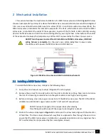
Page 7: ...y only Class 2 power source should be used to power the MSEV series and USHX devices Figure 2 1 MSEV series valve and USHC installation schematic 2 1 Installing a MSEV Series Valve To install the MSEV series valve complete the following steps 1 Pump down and recover any residual refrigerant from the system 2 Remove the current TXV and its bulb or EEV and its controller by cutting Take care to mini...

Page 8: ...tor by brazing Allow the valve to air cool after brazing While brazing direct heat away from the valve body Ensure that the temperature of the valve body does not exceed 221 F 105 C 7 It is mandatory to install a brand new filter drier at the inlet of the MSEV series valve as indicated in Figure 2 1 It can be installed at about 6 away from the valve The MSEV series valve must be protected against ...

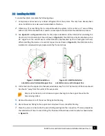
Page 9: ...y the curved green arrows When installing the device on a vertical copper line as shown in Figure 2 4 the USHX cannot be installed at a downward angle represented by the red arrow Figure 2 3 USHX installation orientation on a horizontal copper line Figure 2 4 USHX installation orientation on a vertical copper line 4 Drill a hole into the copper line that extended tubes may fit in to The location o...

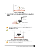
Page 10: ... When torque wrench not available use 7 16 and 9 16 wrenches to tighten the USHX as shown in Figure 2 7 Using two wrenches will ensure that the brazed joint is not damaged during tightening Do NOT turn the power source ON during the installation of the wiring harness Figure 2 7 Installed USHX with attached 10 pin wiring harness 9 Attach the wiring harness 10 pin connector to the USHX as shown in F...

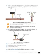
Page 11: ...ermistor body Apply thermal grease between the thermistor and the copper line to obtain the most accurate temperature readings 11 Wrap the thermistor with the insulation material and secure the insulation in place using a zip tie The final result should be similar to what is shown below in Figure 2 9 Figure 2 9 Insulation secured to the thermistor 12 Check for leaks at all the braze joints after b...

Page 12: ...t on 19 Ensure that the settings in the GUI meet the system requirements i e double check the Refrigerant Target Superheat Device Mode and other settings 20 Power on the HVAC R system and the MSEV series valve and USHX will automatically begin functioning 21 Observe the superheat temperature values in the GUI Status tab to ensure that the system is performing nominally Adjust the system settings t...

Page 13: ...ure that the power source voltage matches the MSEV series voltage type If a 12V MSEV series valve is powered by a 24V power source the valve will fail due to an over voltage If a 24V MSEV series valve is powered by a 12V power source the valve will not fully open due to an under voltage 2 Obtain a Class 2 24 VAC transformer with a capacity of 40 to 100 VA and an output of 24 VAC at a frequency of ...

Page 14: ...gure 3 2 The USHX power input wires are non polar so the wire ordering and colors are not significant for the purposes of this step in the procedure All connectors used between the USHX power source and a MSEV series valve should be UL approved The wiring schemes of the Single USHC and MSEV series valve and Single USHS Setup are the same except that the PWM output wires of the USHS for the Single ...

Page 15: ...es to existing structures such as copper and water lines with at least 4 5 sections of electrical tape each Use zip ties on top of the electrical tape in a neat and organized manner to further secure the wires Ensure that all cables are distanced from fans high voltage wires 120 208 VAC and potential areas of water Ensure that any bare cable leads are covered with electrical tape and do not touch ...

Page 16: ... determine what minimum capacity power rating requirements must be met with these power sources based on the number of MSEV series valves installed For the user s own safety only Class 2 power sources should be used to power the MSEV series valves and USHX devices Figure 3 4 Class 2 AC and DC power sources Table 3 1 AC Transformer Minimum Capacity and DC Power Supply Minimum Power Rating Required ...

Page 17: ...tape so that they do not form short circuits with each other or any other wires or metal surfaces As for the Multiple USHCs with Multiple MSEV Series Valves setup process the PWM output wires should be connected to the valves as shown in Figure 3 5 4 Double check the power source output voltage AC transformer secondary or DC power supply output The reading should be at or near 12VDC 24VDC or 24VAC...

Page 18: ...USHX communications Each USHX wiring harness includes RS485 data communication wires 2 wire gray cord that contains a red and a black wire and the green data ground wire 10 Create a daisy chain for the RS485 BUS as shown in Figure 3 5 Connect the gray RS485 communication wire of USHX 1 to USHX 2 Use similar communication cables when extensions are required Do not connect the data ground wire betwe...

Page 19: ...of corresponding MSEV series valve These wires are non polar 18 Additional general purpose wires 20 AWG brown purple wires if they exist on the harness must remain unconnected be terminated using wire nuts and wrapped with electrical tape so that they do not form short circuits with each other or any other wires or metal surfaces 19 Tape any dangling wires to existing structures such as copper and...

Page 20: ...a 10 o clock or 2 o clock position Check that the temperature sensor is wrapped with insulated tape Over Voltage to the MSEV Series Valve Check the resistance across the valve terminals Remove both power connections from the MSEV series valve and measure its resistance with a multimeter The resistance reading should be between 26 34Ω for a 24V valve and between 6 13Ω for a 12V valve If the resista...

Reviews: