C.
Rear Panel
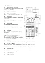
28.
POWER SWITCH
Push marked (1), when you want to operate. The LED (SEE NO.33) will be turned on when working
29.
POWER JACK
This is out of connect the power supply (2 x AC 120V or 230V) jack.
D.
Fault finding guide
Repairing a sound mixing console requires specialist, but basic fault finding is within the scope of any user if a few basic
rules followed.
•
Get to know the block Diagram of your console.
•
get to know what each component in the system is supposed to do.
•
Learn where to look for common trouble spots.
The Block diagram is a representative sketch of all the components of the console; showing how they connect together
and how the signal flows through the system. Once you have become familiar with the various component have gained
a valuable understand of the internal structure of the console and tracking down the problem by elimination.
•
Swap input connections to check that the source is really present. Check both Mic and Line inputs.
•
Eliminate sections of the channel by using the insert point to re-route the signal to other inputs that are known to be
working
•
Route channels to different outputs or to auxiliary sends to identify problems on the master section.
•
Compare a suspect channel with an adjacent channel which had been set up identically .Use PFL to monitor the signal
in each section.
E.
Cautions of installation
Please take care of the following points for installations.
1. Install this product at place of good ventilation and keep an interval over 30cm form the other objects.
2. Install this product at rear side for non-touching of somebody, if possible and avoid an installation of a aisle & the
front side of the stage.
3. Cause an obstacle and an drop of product from the vibration of speaker ,if you put this product one speaker for a
long time.
4. Avoid strong or using product in condition of excessive heat or cold, or in position where it is likely to be subject to
vibration, dust or moisture.
5. Connect the plug into an outlet by the check of power source "AC220V" of the installation place.
6. Install the speaker more front side than the used mic and far away from mic ,if possible.
7. Insert a plug of cord closely into the speaker jack at the speaker connection.
8. Clean this product by using soft dry cloth & poly-wax.
Summary of Contents for HLC Series
Page 1: ...HLC SERIES MIXERS User manual Instrukcja obs ugi...
Page 6: ...H Block diagram...
Page 11: ...H Diagram block...


